Industrial Appliations of Plasma
Fous Radiation
C. Moreno, M.Venere,R. Barbuzza, M.Del Fresno,R. Ramos,
H. Bruzzone, FloridoP.J. Gonzalez, and A. Clausse
InterinstitutionalProgram ofDense Magnetized Plasmas,
CNEA-CONICET-CIC-INFIP-UNMP-UNICEN,Argentina
Reeivedon3July,2001
Appliations ofasmall-hamberPlasmaFous usedas portable radiation generatoris presented.
Thedeviewasdesignedtomaximizetheuene. Themeanneutronyieldwas3x10 8
neutronsof
2.45MeVpershot,orrespondingtoa10 6
neutrons/m 2
ueneontheexternalsurfaeofthe
ham-ber. AtehniquetodetetthepreseneofwaterintheneighborhoodofaompatPlasmaFous
ispresented. Themeasuringsystemisomposedbytwoneutrondetetorsoperatedsimultaneously
oneveryshot. Therstdetetorisusedtoregister thePFneutronyieldineahshot;whereasthe
otheronewas designedfor detetingneutronssatteredbytheblanket. Theresultsindiatethat
thesystemisabletodetetwaterontentsoffewperentsinvolume. Theorrelationoftheounts
reorded by the detetors loated at dierent positions was mappedwith the water distribution
aroundtheneutronsoure. Theompletedetetingsystemisverysimpleandinexpensive.Among
many otherpotential appliations,thetehniqueis speially suitedfor soilhumidityprospetion.
Xraysradiationemitted bythe ompatPlasma FousoperatedinDeuteriumhasbeenusedfor
introspetiveradiographi imagingofmetalliobjets. Thesampleswereloatedabout1maway
fromthePF hamberwall. High-sensitivity,fast-responseommerial radiographi lmwas used
asx-raydetetor. Asetofexperimentalimagesispresenteddemonstratingaveryhighpenetration
powerof the x-ray beam. Among many otherappliations, the presented tehniqueis speially
suitedforintrospetivevisualization ofpieesmanufaturedonmetal.Radiographiprojetionsof
astainless steelBNC elbow takenat 8 dierent angles wereproessedto reonstruttransversal
utsofthe piee. Aomputer tehniquefor 3D reonstrutions was ombinedwith radiographi
imagesof objets X-rayedwith aompatplasma fous. Thetehniqueis able to automatially
determinethepositionoftherotationaxis,reonstrutthe3D-attenuationmap,anddisplayinner
uts. ThesystemwasdemonstratedinintrospetivetomographiimagingofastainlesssteelBNC
elbow.
I Introdution
Plasma Fous (PF) devies ourished in the 70's
and 80's as nulear fusion devies based in the pinh
phenomenonourringduringthepathofhigheletri
urrents through the working gas. The operation of
PFhas beenextensivelystudied byresearh
laborato-riesaroundtheworld,whereseveralPFongurations
has been developed over the years aiming to inrease
the neutron emission [1-4℄. Currently, PF pulsors are
amongtheheapestavailableneutrongenerators,with
uniquefeaturesofextremely shortpulses (hundredsof
ns) that suit them for a number of interesting
appli-ations. There arealso interestingpossibilitiesto take
advantageofx-rays(1-100keV),eletronandionbeams
emittedduringPFshots.
endofoaxialeletrodeswhenanintenseeletrial
dis-hargebetweenthemisinduedbyexternalmeans. The
oaxialeletrodesareloatedinsideavauumhamber
lled with deuterium gas at low pressure. A harged
apaitor bank is onneted to the losed end of the
eletrodesthroughaswith. Afterlosingtheswith,a
gas dishargestarts in thegap between theeletrodes
forming anumbrella-likeplasmalayer. Theazimuthal
magneti eld loatedin the toroidalvolumeenlosed
by the urrent, produes a Lorentz fore that pushes
thesheathtowardtheopenendof theeletrodes. The
run-downoftheurrentsheathisasweepingsupersoni
shokthatpropagatesolletingthegaspartilesahead
of the front. On its arrivalat the open end (some s
aelerating the plasma towardthe axis. Finally, the
sheath lashesontheaxisintheformofasmalldense
plasma ylinder (fous). The lifetime of the fous is
about300ns.
Theemittedneutronsanbeappliedtoperform
ra-diographs[5℄andsubstaneanalysis,takingadvantage
of thepenetrationand ativationproperties ofneutral
radiation[6℄. Likely,theintense x-raypulsesprodued
byfoalizedeletronbremstralungareexellent
andi-dates for radiographyof moving and soft objetsand
formiroeletronilithography[7℄.
Had small portable PF devies beenavailable, the
added value of the emissions would substantially
in-rease,forlargeruenesanbeprovidedinwider
do-mainsofappliations. However,duetothestrong
inter-ation betweenthehotplasmaand thevauum
ham-ber,theeletrodehousingis usuallybig, leavingroom
for the plasma blast. The main trouble with having
theeletrodestoolosetotheontainerwallisthegas
ontaminationwithimpurities,whihonspiresagainst
performaneandregularityoftheemissions[8℄.
Alongthis artile, appliations of the ompat PF
devie, pulsing at one shot per minute is presented.
Theassoiatedx-raysemissionswereappliedtoobtain
three-dimensionalintrospetiveimagesof small
metal-liomponents,andtheemittedneutronswereusedto
detetwaterbyneutroninelastisattering.
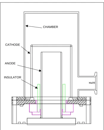
II The plasma fous GN1
ThePlasma-FousGN1 isaompatversionofa
Mather-type mahine. Fig. 1shows adiagram of the
vauum hamberand theeletrodes. The anodeis an
eletrolyti-opperylinder, 38 mmdiameter, 1.5 mm
thik, 87 mm long. The athode is formed by 12
bronzebars,3mmdiameter,100mmlong,ylindrially
plaed,andweldedattheend toabronzering72mm
diameter. The ontainer is a stainless-steel ylinder
157 mm long, 96 mm diameter with a lateral NW25
vauum port for pumping and gas loading. The
insu-lator is aPyrexglass ylinder 35 mmlongand 4 mm
thik.
Usinga mehanialpump and anoildiuser, base
pressures down to 10 8
mbar an be reahed. The
external iruit is a apaitor bank, divided in three
disharging modules; eah of them omposed by ve
Maxwelltype31161ondensers. Thetotalapaitane
is10.5Fandthehargingvoltageis30kV.Thethree
modulesare red simultaneouslyand peakurrentsof
350 kA are attainedin aquarter of period (1.1 s).
CATHODE
ANODE
INSULATOR
CHAMBER
Figure1. ShematisofGN1hamber(sizesaredetailedin
thetext).
Aftereah shot,thellingpressureinreasesabout
0.05 mbar due to the release of impurities from the
hamber,eletrodesandinsulatorwalls. Consequently,
thehamberispumpeddown(mehanially)aftereah
shot in order to assure onstant pressure onditions.
Themaximumshotfrequenywasoneshotperminute,
limited by the harger. Under these onditions, the
frontalwalltemperature(topinFig.1)inreasesabout
20C over the ambient temperature after 30 shots,
ooledpassivelybyairnaturalonvetionandheat
on-dution through the metalli struture. The working
gasisrenewedafter10shots.
Uponommissioning,theequipmentwastestedina
seriesof1000shotsatdierentloadpressures. Thetime
derivative of the urrent owing to the anode, dI/dt,
and the voltage aross the eletrodes, V, were
moni-toredfor eahshot byaRogowskioiland aresistive
voltage divider, and wereregisteredusing a500MHz,
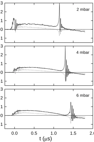
1Gs/sdigitizingosillosope. Fig.2showstypial
sig-nalsfor lling pressuresof 2; 4and 6 mbar. Very
in-tensevoltagespikes(120kV)areobtainedatthetime
wherethemaximumompressiontakesplae,thus
indi-atinggoodfousing. Suhpeaksimposeseveredesign
onditionsontheinsulator,whih should be
onsider-ablythikin ordertostandthestress(2mmofPyrex
glassisdestroyedwithfewdisharges). Itwasobserved
inFig.2thatthefousourslaterforhigherpressures.
Fig.3showstheaveragedependene ofthe fous
design system whih is based in a thermonulear PF
model [9℄. Theontinuous trae isthe foussingtime
derived from an analytial snowplow desription
ou-pledwithanisoentropiplasmaompressionmodel.
-1
0
1
2
3
2 mbar
-1
0
1
2
3
4 mbar
0.0
0.5
1.0
1.5
2.0
-1
0
1
2
3
t (
µ
s)
6 mbar
Figure 2. Signals proportionalto the voltage aross
ele-trodes(solidline)andurrenttimederivative(dottedline).
ThesignalsunitsareVoltsmeasuredinaRogowskioiland
avoltagedividerrespetively.
The time integrated neutron yield was also
mea-sured for eah shot by silverativation response as a
funtion ofpressure. Theneutrondetetor wasplaed
at 60mfrom thefousinaline perpendiulartothe
axis. The sensitive area was 900 m 2
. The neutron
measuringsystemwasalibratedbyomparisonagainst
TLDdetetors. Fig.4showsthedependeneofthe
av-erageneutronyield perpulsewith thellingpressure.
The ontinuous trae on Fig. 4 orresponds to same
model of Fig. 3. The optimumaverage yield, 3 x 10 8
neutrons per shot, ours at 4 mbar. This yield
or-respondsto10 6
n/m 2
pershotintheexternalfrontal
wall.
Dierent insulator lengths were tested in
prelimi-naryseries ofmeasurementsaimed to investigate eah
design performane. It was found that variations of
5mmin that lengthleadto notieabledegradationof
2
4
6
8
0.8
1.0
1.2
1.4
1.6
t
f
(
µ
se
c
)
p
o
(m b )
Figure3. Variationofthefousingtimingwithlling
pres-sure. The line orresponds to preditions of a snowplow
model[9℄.
0
2
4
6
8
0
1
2
3
Y
n
/
1
0
8
P
o
(mb)
Figure4. Neutronsyieldat90 Æ
oaxisasfuntionoflling
pressure. Thelineorrespondstopreditionsofasnowplow
model[9℄.
III Defetosopy
PF an be advantageously used as high-intensity
short-duration x-ray soures. Due to the very fast
plasma ompression attained in these devies,
parti-ularly intensesoftand hardx-rayspulses areemitted.
High repetition rate small PF are urrently used for
SXR lithography[10℄. High-Z working gasesare used
in these appliations to enhane the x-rayyield at
re-duedwavelengths[5℄. Wedeidedtousetheompat
PFoperatedinDeuteriumformakingnon-onventional
radiographs. Our aimis to ndnewappliation elds
forthePFasx-raysoure,andtoallowforthe
possibil-ityofobtaining,inafutureexperiment,asimultaneous
ob-The samples to be imaged were plaed outside
the stainless steel hamber, on the eletrodes
symme-try axis, and 83.5 m away from the foussing region
(Fig. 5). Commerial radiographilm, Curix ST-G2
from AGFA wasused together with AGFA suggested
developerandxerforthislm. Nospeialproedures
wereneededotherthanthosereommendedbythe
sup-plier, tomanipulateanddevelopthelms.
GN 1
Neutron
Generator
Device for
angular variation
X-Ray
Film
Object to
be tomographied
Figure5. Setupofthetomographitehnique.
Astainless steelBNCelbowwas usedasasample.
Alltheshotsweremadeatllingpressuresof4-5mbar
pure deuterium. Thesample wasmounted ona small
aryliplatformthatrotatestoallowfortakingimages
at dierent viewingangles. The rotatingaxis was set
vertiallyand8viewingangleswereused: 0,30,60,75,
90, 105, 120, and 150 degrees. The axis wasmarked
withasharpmetallineedle.
Fig.7showsthe set of radiographsof thepiee at
dierent angles. It anbe seenthat, even ontrolling
arefully theoperation,there are alwaysdierenesin
brightness and foalization. Therefore, in order to be
useful in atomographi system, we should be ableto
reonstrutinnerutsproessingimperfetprojetions.
Figure7. Tomographireonstrutionsusingthe
radiographsshowninFig. 6.
TheMontearlomethodisaexibletehniquethan
antohandlequalitydierenesoftheinformation
in-put. Basially,Montearlotomographireonstrution
is astohasti searhing proess, where the omputer
bounes randomly in the set of all possible digital3D
images (alled instanes), guided with aseletion
ri-terionthat ensurestheonvergene towardthe atual
inner attenuationeld. The reonstrution algorithm
is based on the omparison of the atual radiographs
with the projetions that would produe the instane
image. Thegeneralproedureisasfollows:
Starting with an initial guess instane, modify
slightlythetoneofapixelhosenat random.
Calulate the projetions of the instane in every
diretion.
Calulate an error indiator averaging the square
deviations of the instane projetions respet to the
atualprojetions.
Themethodwasimplementedusingobjetoriented
programming, in visual C ++
. A visualization system
ompletesthetool,allowingthefastinspetionofinner
uts of the attenuation eld. The hardware
require-mentisjustaPentiumpersonalomputer,andthe
sys-tem runs in MS Windows environment. Fig. 7shows
thedisplayofdierentutsof theBNContheontrol
paneloftheappliation. Thevisualizationoftheinner
utsshowsdetailsdownto 0.3-mmresolution.
IV Neutron ehography
Neutrons an be used for deteting Hydrogen in
metalsorfordetetingsubstanesbyativationanalysis
[11℄. Either hugessionreatorsorpowerfuldeuteron
aelerators are used in these appliations as neutron
soures, whih share the disadvantages of being
non-portable and very expensive. On the ontrary,
sub-stane interrogation system should be portable,
reli-able, eonomially ompetitive, and minimize the
en-vironmental impat. PF devies lledwith deuterium
gas,omplementedwithaoupleofneutronidetetors
are a valid alternative, as they fulll all the
require-mentsmentionedbefore.
We onduted an experiment to detet water or
othersubstanesontaininglowZelements,byneutron
inelasti sattering. Themethod is basedonthesame
prinipleofthesonarortheehographs,registeringthe
neutronssatteredbytheinterrogatedsubstane,
om-paringthedetetorresponsewhentheinterrogated
sub-staneisabsent.
The measuring system is omposed by a neutron
pulsedgeneratorandtwosilverativationdetetors
op-erated simultaneously on everyshot. The rst
dete-tor is used to registerthe PF neutron yield; whereas
theotheroneisusedtodetetneutronssatteredbya
waterblanket. TheompatPFdevielledwith
deu-terium wasused to provideneutron pulses. The basi
ideaofthemethodistouseasuitabledetetorto
regis-tertheneutronssatteredbytheinterrogatedsubstane
(ifpresent)andtoontrastthedetetorresponsewhen
theinterrogatedsubstane isabsent. Shotsweremade
inpreseneoftheinterrogatedsubstane,thenthe
pro-edurewasrepeatedafterremovingthesubstane,and
the neutrons registered in both situations were
om-pared.
Fig.8showstheexperimentalsetup. Astandard
sil-verativationounterplaedside-on,60mawayfrom
thePF hamberwasused asthe referenedetetor to
taketheshottoshotvariationoftheneutronyieldinto
aount. This detetor was overed with paraÆn to
moderate the fast neutrons. The seond detetor is
omposed bythreeGeigers,eah ofthemoveredbya
0.3mmthiksilverfoilandplaedinsideametallian
(10m in diameterand 13m inlength). Some
pak-in position inside the an. This detetor wasloated
side-on,approximatelyat30mfromthePFhamber.
7 cm
50 cm
20 cm
DETECTOR 1
PLASMA
FOCUS
WATER
50 cm
75 cm
DETECTOR-2
Figure8. Neutronehointerrogationsetup.
140litersofwaterwerearrangedin awallof11plasti
ontainers. The water wall wasput in dierent
posi-tionsrespetofthedetetorsystems. Forevery
ong-urationthePF wasshotaboutfteen times reording
theountsmeasuredin eah detetor.
Fig.9showstheresultsobtainedalongthePFaxis.
Eahpointin thegraphiorrespondsto oneshot,the
ounts of eah detetor being the oordinates of the
plot. The relativeountingof themoderateddetetor
inreasesasthewater getslosertothedetetion
sys-tem. Thiseetanbeattributedtothehangein the
solid angle oeredbythe water. Theountsolleted
by the sattered neutrons detetor when no water is
present, orrespond to neutrons reeted by the
lab-oratory building. The slopeof the least-squares lines
orresponding to eah position anbe used to
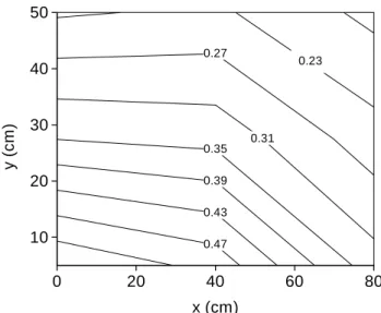
hara-terize thesensitivity ofthe system. Fig.10 shows the
ontour map of the relative ounting slope. The
o-ordinates orrespond tothe loationof thewaterwall
respet to thePFhead. The x-and y-oordinatesare
measuredalonglinesperpendiularandparallelto the
PF symmetry axis respetively. It an be seen that
therelativeountingdereasesfasterwhenthewateris
movedawayalongthesymmetryaxis.
0
500
1000
1500
2000
2500
0
200
400
600
800
1000
7 cm
20 cm
y = 50 cm
water absent
S
c
a
tt
er
e
d n
eutr
ons
(
a
.u.
)
0.27
0.31
0.35
0.39
0.43
0.47
0
20
40
60
80
10
20
30
40
50
0.23
y (
c
m
)
x (cm)
Figure 10. Contour map of therelative neutronounting.
Every(x,y)oordinaterepresentthepositionofthewater.
V Conlusions
Twofeasibilitystudiesofindustrialappliationsof
the X and neutron radiation produed by a ompat
PlasmaFouswerepresented.
Atehniquetodetetthepreseneofwaterwas
de-velopedusingtwoneutrondetetors operated
simulta-neouslyoneveryshot. Theresultsindiatethatthe
sys-temis ableto detetwaterontentsof fewperentsin
volume. Theomplete detetingsystemisverysimple
andinexpensive. Amongmanyotherpotential
applia-tions,thetehniqueisspeiallysuitedforsoilhumidity
prospetion.
On the other hand, X-rays from the PF has been
used for introspetive radiographi imaging of
metal-li objets. Thetehniqueis speially suitedfor
intro-spetivevisualizationofpieesmanufaturedonmetal.
RadiographiprojetionsofastainlesssteelBNCelbow
takenat8dierentangleswereproessedtoreonstrut
transversal uts of the piee. A omputer tehnique
for3Dreonstrutionswasombinedwithradiographi
images of objetsX-rayed with a ompat plasma
fo-us. Thetehniqueisableto automatially determine
the position of the rotation axis, reonstrut the
3D-attenuationmap,anddisplayinneruts.
Referenes
[1℄ A. Bernard, Nulear InstrumentsMethods, 145, 191
(1977).
[2℄ H.Conrads,Pro.3 rd
LatinamerianWorshopPlasma
Phys.,Santiago, Chile,July18-29(1989).
[3℄ A.SerbanandS.Lee.Experimentsonspeed-enhaned
neutronyieldfromaplasmafous.J.PlasmaPhysis,
60,part1,3-15(1998).
[4℄ G.Deker,R.Wieneke,Physia82C,155-164(1976).
[5℄ M. Gibbons, W. Rihards and K. Shields.
Optimiza-tionofneutrontomographyforrapidHonentration
inspetion of metal astings, LLNL Rep
UCRL-JC-129723,(1998).
[6℄ E. Hussein and E. Waller. Review of one-side
ap-proahestoradiographiimagingfordetetionof
explo-sivesand narotis, Radiation Measurements, 29(6),
581,(1998).
[7℄ S.Lee,V.Kudryashov,P.Lee,G.Zhang,A.Serban,M.
Liu,X.Feng, S.Springham,T.Wong andC.Selvam.
SXR Lithography Using a High Performane Plasma
FousSoure,1998ICPPand25EPSConfonContr.
FusionandPlasmaPhysis,22C,2591 (1998).
[8℄ J.Gratton,M.Alabraba,A.WarmateandG.Giudie,
Deterministi dynamis of Plasma Fous disharges.
Chaos,Solitons&Fratals,3,343(1993).
[9℄ C.Moreno, H.Bruzzone,J.MartnezandA. Clausse.
Coneptual engineering of plasma-basedneutron
pul-sors.IEEETransationsonPlasmaSiene,28,
1735-1741(2000).
[10℄ S.Lee,P.Lee,G.Zhang,X.Feng,V.Gribkov,M.Liu,
A.Serban,andT.Wong.HighRepRateHigh
Perfor-manePlasmaFousas aPowerfulRadiation Soure.
IEEETransonPlasmaSi,26,1119,Aug(1998).
[11℄ F.Brooks, A. Buer, M. Allie,K.Bharuth-Ram,M.
NhoduandB.Simpson,DeterminationofHCNO
on-entrationsbyfastneutronsatteringanalysis,Nulear
Instruments and Methods Set. A (410) 2, 319-328