Theoretial Studies of Non Indutive
Current Drive in Compat Toroids
R.Farengo, A.F. Lifshitz, K.I. Caputi,N.R. Arista,
CentroAtomioBariloheandInstitutoBalseiro
S.C.de Barilohe,RN,Argentina
and R.A. Clemente
Institutode FsiaGlebWataghin
UniversidadeEstadualde Campinas
Campinas,SP, Brasil
Reeivedon26June,2001
Threenonindutiveurrentdrivemethodsthatanbeappliedtoompattoroidsarestudied.The
use of neutral beams to drive urrent ineld reversed ongurations and spheromaksis studied
usingaMonteCarloodethatinludesaompleteionizationpakageandfollowstheexatpartile
orbitsinaself-onsistentequilibriumalulatedinludingthebeamandplasmaurrents.Rotating
magneti eldsare investigated as a urrent drive methodfor spherial tokamaks by employing
atwodimensional modelwithxed ionsand masslesseletrons. Thetimeevolutionof theaxial
omponentsofthemagnetieldandvetorpotentialisobtainedbyombininganOhm'slawthat
inludestheHalltermwithMaxwell'sequations. Theuseofheliityinjetiontosustainauxore
spheromakisstudiedusingtheprinipleofminimumrateofenergydissipation. TheEuler-Lagrange
equationsobtained usingheliity balaneas aonstraintare solvedto determinetheurrent and
magnetieldprolesoftherelaxedstates.
I Neutral beam urrent drive
The use of neutral beams to sustain the urrent in
a eld reversed onguration (FRC) reator was
pro-posed many years ago [1℄. More reently, laboratory
experiments where a neutral beam is injeted into an
existing FRC havebeenperformed[2℄. Unfortunately,
thelifetime of these experimentsismuh shorterthan
the slowingdown andthermalizationtimes and
there-foreourresults,whihapplytoasteady-statesituation,
annotyetbeomparedwiththeexperimental
observa-tions. Spheromaksareformedandsustainedbyheliity
injetionandtheuseofalternativemethodsisgenerally
not onsidered. However, usingneutralbeamsto
pro-duepartoftheurrentouldreduetheamplitudeof
the utuationsrequired for heliity injetion urrent
drive thus improving the onnement. This behavior
has been observedin reent RFP experiments [3℄. In
addition, the use ofneutral beams will resultin
addi-I.1 Monte Carlo ode and equilibrium
The Monte Carlo ode employed in this study
fol-lowsthe trajetoriesof an ensemble of beam partiles
movingin aself-onsistentMHDequilibrium. The
ex-at orbits are needed beause the large radial
exur-sions of the energeti beam partiles prevent the use
of gyro-averaging. Neutral partiles are injeted and
theodealulatestheirionization,stoppingand
ther-malization. Thisinformationisusedtoreonstrutthe
spatial distribution of the beam density, urrent and
transferredpowerandfore insteadystate.
Theionizationproessesinludedareionizationby
Coulomb ollisionswith ions and eletrons, ionization
by harge exhange and multistep proesses: i.e.,
ex-itationfollowedbyionization. Theeet ofCoulomb
ollisionsisdesribedusingaFokker-Plankollision
op-erator and the momentum and energy transferred to
eletronsandionsareevaluatedseparately. The
netiaxis. It isassumed tobeoldandnon divergent
andisonsideredto beapointsoure(negligibleross
setion). Settingthevaluesoftheneutralinjetion
ur-rent(I
N
), theenergy of thebeam partiles(E
N ) and
the impatparameter (b), thebeamis ompletely
de-termined.
x
y
z
r
Beam
s
b
Figure1. Injetiongeometry.
The plasma equilibria are solutions of the
Grad-Shafranov equation with an extra term representing
the beamurrent density. We assume that the beam
pressureissmallomparedto theplasmapressureand
thereforenegletthebeamontributiontothepressure.
Thetemperatureisonsidereduniformandequalto500
eVforbotheletronsandions. Withthese
approxima-tions,theGrad-Shafranovequationanbewrittenas:
r
r 1
r r +
2
z 2
= 16
3
r 2
dP
d 8
2
2
dI 2
d 8
2
r
j
b (1)
where is thepoloidal ux funtion,I isthepoloidal
urrent (setto zerofor FRCs), j
b
is thebeamurrent
densityandP istheplasmapressure. Weassumethat
the pressure and poloidal urrent are related to the
poloidaluxthough:
P( )=G
0 "
0 D
2
0
2 #
I 2
( )=I 2
0
0
2
(2)
whereG
0 andI
0
areonstants,
0
isthemagnetiux
atthemagnetiaxisandDisthehollownessparameter.
Theequation is rstsolved withj
b
=0and G
0 is
de-terminedbyrequestingthatB
z (r
s
;0)=B
0
. This
equi-partiles. Then, we run the Monte Carlo ode with
this equilibrium and alulate j
b
. Introduing j
b into
eq.(1)anewequilibriumis alulated. Thisproedure
isrepeateduntil thesolutionsonverge.
I.2 Ionization and trapping
In the ode, a partile is onsidered lost when it
reahesthe ends ofthe plasma orwhen itsradius
be-omeslargerthanthewallradius. FortheFRC
param-eters onsidered in this study, the fration of neutral
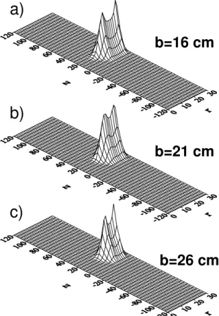
partilesthat isnotionizedisnegligiblesmall. For
in-jetionenergiesbelow40keV,thelossesaresigniant
only for b & 27m. As E
N
inreases, the maximum
impatparameterwhih resultsinompleteionization
beomessmaller. Thepartiles reah thehigh density
region even when ionization ours farfrom there; all
thepartilesinjetedwithbbetween15and25mross
thenull. ThisisseeninFig. 2whihshowsthespatial
distributionofbeamionsafterompletingtheirrst
or-bit. Itislearthattherearesigniantdiereneswith
respettodevieswithalargetoroidaleld,wherethe
beamenergyandtheinjetiongeometryareseletedin
orderto trapthebeamlosetotheplasmaore.
b=26 cm
b=16 cm
b=21 cm
a)
b)
c)
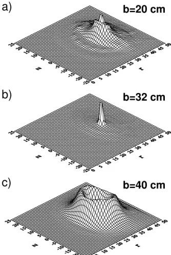
Thesituationin spheromaksis dierentdueto the
preseneofatoroidaleldandalosettingux
on-server. Partilesionizedinsidetheseparattrixan
nev-erthelesshitthewalldueto theirlargeLarmorradius.
In addition, thetoroidal eldproduesafundamental
hange in the behavior of the partiles. This an be
seen omparing Fig. 3, with Fig. 2. For b smaller
than the radius of the magneti axis (32 m)
ioniza-tion an our over a wide region and this results in
abroadinitialpartile distribution. Whenb=32m,
mostpartilesareionizedandtrappedlosetothe
mag-neti axis. Finally, when b > 32 m the partiles are
trappedinorbitsthatosillatearoundagivenux
sur-fae. Theamplitudeofthis osillationdepends onthe
injetion energy. Anotheronsequeneof thepresene
of a toroidal eld is that a fration of the partiles,
whihdepends onthe injetionenergyandb,beomes
trappedinbananatypeorbits. ThisisshowninFig. 4,
whih presentsa plot of lost and trapped partiles as
afuntion oftheinjetionenergyforthreevaluesofb.
Atlowinjetionenergy,alargefrationofthepartiles
beometrapped inbananaorbitswhile athigh energy
the dominant eet is partile losses due to ollisions
withthewall.
b=20 cm
b=32 cm
b=40 cm
a)
b)
c)
Figure3.Spheromak,spatialdistributionofbeamionsafter
20
40
60
80
100
15
20
25
30
35
40
45
50
55
b=20 cm
b=32 cm
b=40 cm
L
o
ss
+
B
anan
a (
%
)
E (keV)
Figure4. Spheromak,lostandtrappedpartilesasa
fun-tionoftheinjetionenergy.
I.3 Current drive
Fig. 5showsthebeamplasmaurrentasafuntion
oftheinjetionurrent(Fig. 5a)andenergy(Fig. 5b)
forFRCswithhollow(D=0:5)andpeaked(D= 10)
proles. Atlowinjetionurrentthebeamurrent
in-reaseslinearly. Athigherurrents,thedeviationfrom
alineardependene is due to theinreasein theloal
eldanddensityprodued bythebeamurrentin the
highplasma. Thiseetismorenotieableforpeaked
equilibria. Thedependeneofthebeamplasmaurrent
ontheinjetionenergyisompliatedduetothe
varia-tionoftheionizationrosssetion andstoppingpower
withenergy. Athigh energy,thebeamplasmaurrent
issigniantlysmallerforpeakedequilibriadue tothe
higherdensityproduedbytheeetdisussedabove.
In spheromaks, the beam plasma urrent shows a
strongerdependene upon theimpat parameterthan
inFRCs. This isseenin Fig. 6awhihpresentsaplot
ofI
b
asafuntion ofbforE
N
=20keV andI
N =100
A. Themaximumurrentisobtainedwhenbis
approx-imatelyequal to the radius of the magnetiaxis (b
0 ).
Thisistheresultofaompetitionbetweentwoeets.
Whenbislargerorsmallerthanb
0
,thefrationoflost
plustrappedpartilesinreasesasshowninFig. 4. On
theotherhand,thedensityandstoppingare largerat
themagneti axis. Fig. 6bshowsthatat lowinjetion
urrent(I
N
<100A)I
b
inreases almost linearlywith
I
N
and that ,again, the maximumurrentis obtained
whenb=b
0
. Thedependene of I
b
withthe injetion
energyis shown in Fig. 6 for threevalues of the
im-patparameter. Theasewith b=b
0
0
50
100
150
200
250
300
0
20
40
60
80
100
D=-10
D=0.5
I
b
(k
A
)
I
N
(A)
10
20
30
40
50
0
10
20
30
40
50
60
70
80
D=-10
D=0.5
I
b
(k
A
)
E (keV)
a)
b)
Figure5. FRC,beamplasma urrentas afuntiononthe
injetionurrentandenergy.
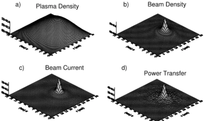
Fig.7showsthespatialdistributionsofplasmaand
beam densities, beam urrent and transferred power
for a peaked FRC equilibrium with E
N
= 20 keV,
b =21m and I
N
= 100 A. The peak in theplasma
densityisduetotheeetofthebeamurrentuponthe
equilibrium disussedabove. Thebeamdensityshows
two radial peaks whih are due to fat that in their
radialosillationsthepartilesspendmoretimeatthe
turningpointsthusinreasingthedensityinthisregion.
A similar eet an be observed in the beam urrent
distribution. Thepowertransferredtotheplasmadoes
not show two peaks beause itdepends upon the
val-uesofthebeamand plasmadensities. Inthis asethe
peakintheplasmadensityislargeenoughtooverame
thedouble peakedstruture ofthebeamdensity. Fig.
8 shows similar plots for a spheromak with the same
values of I
N and E
N
and b =32 m. It anbe seen
that the plasma density does not hange appreiably
due to the beam and that the beam urrent, density
and powerremain well loalized aroundthe magneti
axis.
20
22
24
26
28
30
32
34
36
46
48
50
52
54
56
58
60
I
b
(k
A
)
b(cm)
0
20
40
60
80
100
0
20
40
60
80
100
120
b
=20 cm
b
=32 cm
b
=40 cm
I
b
(k
A
)
I
N
(A)
20
40
60
80
0
50
100
150
200
250
b
=20 cm
b
=32 cm
b
=40 cm
I
b
(k
A
)
E
N
(keV)
a)
b)
c)
Figure 6. Spheromak, beamplasma urrent as a funtion
oftheimpatparameter,injetionurrentandinjetion
en-ergy.
Plasma Density
Beam Density
Beam Current
Power Transfer
a)
d)
c)
b)
Figure 7. FRC, spatial distribution of plasma and beam
densities,beamurrentandtransferredpowerfor EN=20
Plasma Density
Beam Density
Beam Current
Power Transfer
a)
d)
c)
b)
Figure 8. Spheromak, spatial distribution of plasma and
beam densities, beam urrent and transferred power for
E
N
=20keV,b=32mandI
N
=100A.
II Rotating magneti eld
ur-rent drive in spherial
toka-maks
Rotating magneti elds (RMF) have been used to
driveurrentin Rotamaks[4℄ andFRC[5℄. Although
thesedeviesgenerallyoperatewithoutastationary
az-imuthal(toroidal)magnetield,somerotamak
experi-mentsinludedaondutorattheaxisofthedisharge
vessel, produing ongurations whih are similar to
spherial tokamaks (ST) [6℄. Due to the urrent
in-terestin STs, whih haspromptedthe onstrutionof
severalnew devies, the developmentof RMF urrent
driveasan eÆientmethodfor this oneptwould be
ofgreat importane.
II.1 Physial model and equations
Theongurationonsideredis showninFig. 9. It
onsistofaninnitelylongannularplasmaolumnwith
inner radiusr
a
andouterradius r
b
. Insidetheolumn
r<r
a
thereisauniform,stationary,axialurrent
den-sitythat produesthevauumtoroidaleld. Theoils
thatproduethetransverse,rotatingmagnetieldare
assumed to be far from the plasmaand their eet is
introdued viatheboundaryonditionsimposed at r
(r
>> r
b
). The ions are onsidered to be xed and
the eletrons are desribed using an Ohm's law that
ontainstheHallterm:
r
a
r
b
r
c
Figure9. Crosssetion oftheongurationemployed.
E=j+ 1
en
(jB) (3)
where is the resistivity, whih weassume to be
uni-form. UsingOhm's lawand Maxwell'sequations aset
of oupled equations for B
z and A
z
anbe obtained.
Sinethe ontribution of the uniform axial urrent to
A
z
anbealulatedanalytially,weseparateA
z intwo
parts: A
z = A
z;va +A
z;pl
, where A
z;va
ontains the
ontribution of the stationary axial urrent and A
z;pl
theontribution of the plasma and the externaloils.
Assumingthattherotatingmagnetieldproduedby
theoils anbewritten as:
B rot
r
= B
!
os(!t )
B rot
= B
!
sin(!t )
andnormalizingthetimewith!,theradiuswithr
b and
theamplitudeofthemagnetieldwithB
!
weobtain
thefollowingset ofdimensionlessequations:
B
=
1
2 2
r 2
B+
^ r
^r r
2
A
A
r
2
A
A
^r B
tor
^ r
(4)
A
=
1
2 2
r 2
A+
^ r
A
^r B
tor
^ r
B
A
B
^r
(5)
where:
^ r=
r
r
; =!t; B =
B
z
B
; A=
A
z;pl
B r
d
andB
tor
isthevauumtoroidaleldatr^=1,
normal-izedto B
!
. Thetwodimensionless parameters, and
,aredenedas:
= r b Æ =r b 0 ! 2 1=2 ; = !;e e;i = B ! en
whereÆisthelassialskindepth,
!;e
istheeletron
ylotron frequeny alulated with the amplitude of
theRMFand
e;i
istheeletron-ionollisionfrequeny
( e;i =ne 2 =m e
). When>>1, theeletronsanbe
onsidered magnetized by the RMF. Knowing A and
B, the other magneti eld omponents and the
ur-rentdensityanbeeasily alulated.
II.2 Numerial method and boundary
onditions
The omputational domain is divided in three
re-gions. In 0 ^r < ^r
a
, region I, there is a uniform
axial urrent and no plasma. Sine A ontains only
theontribution oftheplasmaandtheRMF wehave:
r 2
A =0. Sine there are noazimuthal orradial
ur-rents in this region, B must be uniform (but an be
time-dependent). Inside the plasma, r^
a
< ^r < 1,
re-gionII,wesolve Eqs. 4and 5. In 1<^r <r^
, region
III, there is vauum and therefore B is uniform and
r 2
A=0.
Atr^=r^
weset:
A(^r
)=r^
sin( ) 1 e = 0 ; (7)
wheretheexponentialisintroduedtoallowforaslow
"turn on" of the rotating eld and ^r
is taken large
enoughfortheresultsto beindependentofitsspei
value. Atr^=1and ^r=r^
a
, theradialderivativeofA
must be ontinuous (B
= A
z
=r). To obtain the
resultspresentedbelow,thevalueofBinregionIIIwas
keptonstantthroughouttheomputationbutitisalso
possibleto introdueauxonserverandadjustB
af-tereahtimesteptosatisfyaxialuxonservation. In
regionI,Bisuniformbutnotonstant(intime)andwe
alulate itsvalueusing Stoke'stheorem. Considering
airumferene ofradiusr^
a
+h,where histheradial
gridspaingin regionII,weanwrite:
B(I)B(^r
a )= 1 r^ 2 a ( Z 2 0 A (^r a
+h;)r^d Z ^ ra+h ^ r a
d^rr^ Z
2
0
dB(^r;) )
(8)
d
The equation for the evolution of A
in region II is
obtained from the -omponent of Ohm's law, using
E=-A=t.
II.3 Results
Normalizedquantitiesareemployedintheplots
pre-sentedbelowand the eÆieny is dened as theratio
between the azimuthal plasma urrent and the
ur-rent that would be produed if all the eletrons
ro-taterigidly with frequeny!. Fig. 10 isaplot ofthe
steady-stateeÆienyvs. B
tor
for =16:6;=11:07
and r
a
= 0:15: The eÆieny is 1, as in FRCs, when
B
tor
=0anddereasesto0.15forB
tor
=10. Itshould
benoted,however,that duetothelargerradiusofthe
plasmainatokamak,asomparedwithanFRC,an
ef-ienyof0.15ouldstillresultinasigniantplasma
urrent. Fig. 11 presents a similar plot for = 14:9
andthesamevaluesofandr
a
asFig.10. InanFRC,
the same values of and result in inomplete eld
in Fig. 11 that forsmall values ofB
tor (B
tor
.1:26)
therearetwosteady-statesolutions. Theinitial
ondi-tions determine thebranh towardswhih the system
evolves. IfwesetB
tor <B
rit
tor
andstartwithaplasma
olumnthathasnoazimuthalurrent,thesteady-state
solutionfollowstheloweÆienybranh(dashedline)
inFig. 11. WhenB
tor
beomeslargerthantheritial
value,andthesameinitialonditionsareemployed,the
eÆieny ofthesteady-statesolutionjumpstothefull
line in Fig. 11. Toaess thehigh eÆieny solution
for B
tor
less than the ritial value (dotted line) it is
neessaryto startwith asteady-state solutionhaving
B
tor > B
rit
tor
and slowly derease B
tor
. The
eÆien-ies obtainedin the high eÆieny branh of Fig. 11
( =14:9),areverysimilartotheeÆieniesobtained
with = 16:6 (Fig. 10). This indiates that, in the
preseneof asteadytoroidaleld, plasmashaving
dif-ferentvaluesofandisplayaverysimilarbehavior. In
fat,thesimilaritybetweenthehigheÆienyregimeof
Fig. 11and theregimeof Fig. 10extendsto theother
et.). Inwhatfollowswewillonsidertworegimes: the
regimeofFig. 10,with=16:6,andtheloweÆieny
regime ofFig. 11,with=14:9
0
2
4
6
8
10
0.0
0.1
0.2
0.3
0.4
0.5
0.6
0.7
0.8
0.9
1.0
e
ff
ici
en
cy
B
tor
Figure10. EÆienyvs. steadytoroidaleldfor=16:6;
=11:07and^ra=0:15.
0
2
4
6
8
10
0.0
0.2
0.4
0.6
0.8
1.0
ef
fi
ci
en
cy
B
tor
Figure11. EÆienyvs. steadytoroidaleldfor=14:9;
=11:07and^ra=0:15.
The eet of the steady toroidal eld on the
az-imuthal urrent density prole is shown in Fig. 12,
whihpresentsaplotoftheaveraged(over)j
vs. r
forthesameparametersasFig. 11andthreevaluesof
B
tor
. WhenB
tor
=0(fullline)thereisalargeregion,
up to r
= 0:5, inside the plasma with negligible
ur-rentdensityandanarrowregion,r 0:9, onthe
out-side where the eletronsrotate rigidly with frequeny
!. WhenB
tor
=0:5(dashed line)the urrentdensity
inreases on the inside, in the region 0:3 r 0:5,
and dereases for r 0:6, giving an overall inrease
inthetotalplasmaurrent. Finally,whenB
tor
=1:15,
theurrentdensityisomparabletothatobtainedwith
B
tor
=0 forr0:6 andsigniantlysmallerat larger
radius. The ase with = 16:6 is shown in Fig. 13,
whihalsopresentsaplotof<j
>vs. rfor3valuesof
B
tor
. When B
tor
= 0the eletronsrotate rigidlyand
aregionwithnegligible,evenreversed,urrentdensity
appearsresultinginaredutioninthetotalurrent. As
B
tor
inreasesfurtherthewidthofthisregioninreases.
0.0
0.2
0.4
0.6
0.8
1.0
-16
-14
-12
-10
-8
-6
-4
-2
0
2
B
tor
=0
B
tor
=0.5
B
tor
=1.15
<j
θ
>
r
Figure12. Averaged(over)azimuthalurrentdensityas
a funtionof normalized radius for = 14:9; = 11:07,
^ r
a
=0:15(loweÆienybranh).
0.0
0.2
0.4
0.6
0.8
1.0
-16
-14
-12
-10
-8
-6
-4
-2
0
2
B
tor
=0
B
tor
=4
B
tor
=8
<j
θ
>
r
Figure13. Averaged(over)azimuthalurrentdensityas
a funtionof normalized radius for = 16:6; = 11:07,
^
ra=0:15(higheÆienybranh).
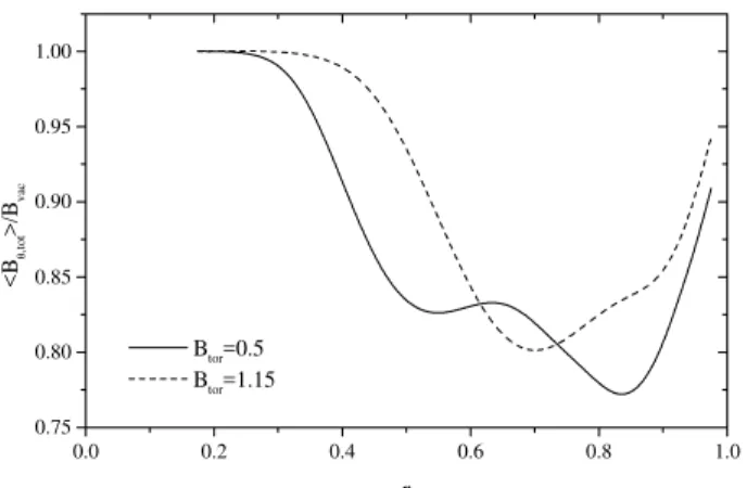
Experimental measurements and theoretial
alu-lations in ongurations with a steady toroidal eld
have shown the existene of poloidal urrents, whih
are generally diamagneti. We studied this issue for
the two onditions indiated above. For the low
eÆ-ienyregime of Fig. 11 thereis asigniant
diamag-neti eet, whih is shown in Fig. 14. This gure
presentsaplotoftheratiobetweentheaveraged(over
) azimuthal eld and the vauum eld as afuntion
ofr. ForB
tor
=0:5thediamagnetiwellextendsfrom
r
=
0:3totheouterplasmaboundary,withamaximum
redutioninthetotaleldofover20%(omparedwith
the vauum value). For B
tor
= 1:15 the width and
depth of thewellderease but the diamagnetism
0.0
0.2
0.4
0.6
0.8
1.0
0.75
0.80
0.85
0.90
0.95
1.00
B
tor
=0.5
B
tor
=1.15
<B
θ
,to
t
>/B
va
c
r
Figure 14. Ratio between the averaged, total, azimuthal
eld and the vauum eld for = 14:9; = 11:07 and
^
ra=0:15(loweÆienybranh).
II.4 Disussion
As a rst step towards assessing the possibility of
using RMF urrent drive in STs, we studied the
ef-fet of a steady toroidal eld on this method. Our
work presentstwomain improvementswhenompared
topreviousstudies. Therstistheuseofa
ongura-tionwhih, albeit2D, inludes aholeat the enter of
theplasmathusprovidingabetterrepresentationof a
tokamak. The seond is the use of afully 2D
numer-ial ode whih solves the time dependent equations
obtainedfromthebasiphysialmodelwithoutfurther
assumptions.
Although we did not attempt to make a detailed
omparisonwiththeexperimentalresultsofRef. [6℄,it
islear thatmany ofthequalitativefeatures observed
in these experiments are reprodued by the low
eÆ-ieny branh of Fig. 2. Our results show that for
somevaluesoftheexternaltoroidaleld,therearetwo
steady-statesolutionswithdierenteÆienies. When
thesteadytoroidaleldislargeomparedtothe
rotat-ingeld,aseofinterestforSTs,theeÆienyissmall
but the total urrent ouldstill be signiant if
oper-ation at frequeniesoftheorder of 10 6
Hzis possible.
Furtherstudiesshouldbedonetondthebest
operat-ingregimeforSTsandtheorrespondingeÆienyand
requiredpower. Inaddition,improvedphysialmodels
should bedevelopedtoremovesomeof themost
riti-alassumptionsemployedinthisstudy. A stepinthis
diretionhasbeenreentlydonebyMilroy[8℄who
em-ployedan MHDmodel tostudy RMF urrentdrivein
FRCs.
III Minimum dissipation states
for ux ore spheromaks
sus-tained by heliity injetion
Theuse ofheliity injetionto sustainaspheromakis
veryattrativebeause of its simpliity and high
eÆ-ieny. Ingeneral,heliityinjetionurrentdriveis
ex-plained byassuming that the plasma undergoes some
formofrelaxationthatallowsforaredistributionofthe
magneti ux. In this ontext, relaxation priniples
provide a relatively simple method to predit the
-nalstateofplasmasdrivenbyheliityinjetion. Taylor
andTurner[9℄appliedthewellknownminimumenergy
prinipletoauxorespheromaksustainedbyheliity
injetion through the polar aps. Although this
prin-iple has been suessful at explaining the reversal of
themagnetieldintheRFP,itsuseindrivensystems
remainsquestionable. Insuhsystems,otherpriniples
that allow for the introdution of balane onstraints
(injetionrate=dissipationrate)ouldbemore
appro-priate. One suh priniple, the prinipleof minimum
rate of energy dissipation, has been already used to
alulate the relaxed states of tokamaks sustained by
heliityinjetion[10℄[11℄.
Inthis paperweemploythe prinipleof minimum
rate of energy dissipation to alulate relaxed states
of a ux ore spheromak sustained by heliity
inje-tion. Althoughthegeometryonsideredisverysimple,
theresultouldbeofinterestforthereentlyproposed
PROTO-SPHERAexperiment[12℄.
III.1 Minimization, Euler-Lagrange
equations
We assume that the plasma is stationary (v =
0) and minimize the Ohmi dissipation rate
sub-jet to the onstraints of heliity balane (injetion
rate=dissipation rate) and rB = 0. This is done
byintroduingthefollowingfuntional:
W = Z
j 2
dV
0 Z
jBdV+ I
'BdS
Z
where istheplasmaresistivity,'istheapplied
ele-trostati potentialand and areLagrange
multipli-ers. In eq.(9), the rst three terms in the RHS are,
respetively, the Ohmi dissipation rate, the heliity
dissipationrateandtheheliityinjetionrate. Setting
the rst variationof W equalto zero theanellation
of thevolumetermgivesthefollowingEuler-Lagrange
equation:
rj j+
0
2
r=0 (10)
the boundary onditions needed to solve this
equa-tion are obtained from the physial situation
onsid-ered (ux orespheromak sustained by heliity
inje-tionthroughthepolaraps)andfrom theanellation
ofthesurfaetermin ÆW.
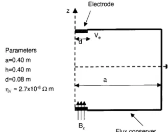
III.2 Results
Equation(10)is solved numeriallyusing
ylindri-aloordinates(=0)fortheongurationshown
in Fig. 15, whih onsists in a ylindrial ux
on-serverwith radiusequalto its height(0.4 m) andtwo
eletrodes. Theradius ofthe eletrodesis onefthof
the radius ofthe ux onserverandit is assumed, for
simpliity, that the magnetield ontheeletrodesis
uniformandisanexternallyontrolableparameter. In
reality,theuxpassingthroughtheeletrodesdepends
ontheurrentowingintheexternaloils(notshown)
and the plasma urrent. Our assumption is that the
urrent in the external oils is adjusted until the
de-siredeld ontheeletrodesisobtained.
Themethodofsolutiononsistsin guessingavalue
for and solving the Euler-Lagrange equations.
Us-ing the alulated urrent and magneti eld proles,
the heliity injetion and dissipation rates are
alu-lated and ompared. If they agree the value of is
aepted, if not a newvalue is hosen and the
proe-dure repeated. Fig. 16 shows ux ontours obtained
for V
e =B
z = 10
3
V=T. The solutionin Fig. 16 a has
=12:2157m 1
andanenergydissipationrate(W
dis )
of 1:56 10 12
W while the solution in Fig. 16 b has
= 12:2223 m 1
and W
dis
=1:6010 12
W. It is lear
that altoughbothare solutionsof theEuler-Lagrange
equations(bothareextremaofthefuntional), the
so-lution thatminimizesthedissipationrateistheonein
Fig. 16 a. For 12:2157m 1
<<12:2223m 1
solu-tions with almost no open ux are obtainedbut they
Figure15. Congurationemployedfortheuxore
sphero-mak.
Fig. 17 showsasequene of solutionsobtainedfor
dereasingvaluesof V
e =B
z
. It islear thatdereasing
V
e =B
z
redues the size of the losed ux region. The
behaviorof the Lagrangemultipliers orresponding to
thesolutionswithhighandlowdissipationisshownin
Fig. 18, whih presents a plot of as a funtion of
log(V
e =B
z
). It is seenthat both valuesare verylose
and that the dierene between them dereases when
V
e =B
z
dereases. Infat,bothvaluesof areloseto
theeigenvalueoftheequationrj=jwithj:^n=0
at the boundary for elongation equal to 1 [13℄. Fig.
19presentsaplotofthetotalplasmaurrent(onopen
andlosedsurfaes)asafuntionoftheappliedvoltage
forB
z
=0:1T. Thisgureshowsthatsigniant
ur-rentsan be obtainedfor reasonablevalues of applied
voltageandmagnetield. Ofourse,thiswilldepend
on the value of the resistivity, whih was assumed to
be2:710 6
minthis alulation. Toonlude,we
present in Fig. 20 2D plots of the toroidal magneti
eldandthetoroidalurrentdensityfortheminimum
dissipation solution with V
e
= 1000V and B
z = 1T
(seeFig. 16). This showsthat ifalargeenough
mag-neti eld anbeprodued largeurrentsouldresult
0,010
0,020
0,030
0,04
0,05
0,06
0,07
0,08
0,09
0,05
0,10
0,15
0,20
0,25
0,30
0,35
0,40
-0,20
-0,15
-0,10
-0,05
0,00
0,05
0,10
0,15
0,20
z(m
)
r(m)
-0,05
-0,04
-0,03
-0,024
-0,015
-0,006
0,0030
0,012
0,021
0,05
0,10
0,15
0,20
0,25
0,30
0,35
0,40
-0,20
-0,15
-0,10
-0,05
0,00
0,05
0,10
0,15
0,20
z
(m)
r(m)
a
b
Figure16. Fluxsurfaesfor thetwosolutionswithV
e =B
z =10
3
V=T.
0,0026
0,005
0,008
0,010
0,013
0,016
0,018
0,021
0,023
0,05 0,10 0,15 0,20 0,25 0,30 0,35 0,40
-0,20
-0,15
-0,10
-0,05
0,00
0,05
0,10
0,15
0,20
z(
m
)
r(m)
0,010
0,020
0,030
0,04
0,05
0,06
0,07
0,08
0,09
0,05 0,10 0,15 0,20 0,25 0,30 0,35 0,40
-0,20
-0,15
-0,10
-0,05
0,00
0,05
0,10
0,15
0,20
z(
m
)
r(m)
0,007
0,014
0,021
0,028
0,04
0,04
0,05
0,06
0,05 0,10 0,15 0,20 0,25 0,30 0,35 0,40
-0,20
-0,15
-0,10
-0,05
0,00
0,05
0,10
0,15
0,20
z(
m
)
r(m)
0,04
0,09
0,13
0,18
0,22
0,27
0,31
0,36
0,40
0,05 0,10 0,15 0,20 0,25 0,30 0,35 0,40
-0,20
-0,15
-0,10
-0,05
0,00
0,05
0,10
0,15
0,20
z(
m
)
r(m)
a
b
c
d
Figure17. Fluxsurfaesofthesolutionsobtainedfor variousvaluesofV
e =B
Figure18. ValueoftheLagrangemultiplierasafuntionof
log(V
e =B
z ).
Figure19. Plasmaurrentasafuntionofappliedvoltage
forBz=0:1T.
III.3 Disussion
We have shown that the relaxed states of a ux
ore spheromak alulated using the minimum
dissi-pation priniple have losed ux surfaes and
signi-ant plasma urrent. Although there are solutionsof
the Euler-Lagrangeequations whih satisfy the
heli-ity balane onstraint and have the open ux region
ontheoutside,theyhavehigherdissipationratesthan
thosewiththeopenuxontheinsideandthereforean
notbeonsideredastruesolutionsoftheminimization
problem. The Lagrange multipliers of both solutions
are very lose and their value is approximately equal
to theinverseof theeletroderadius. Future work on
thisproblemshouldinludetheuseof
anisotropi/non-uniform resistivity.
Aknowledgements
This work was partially supported by grantsfrom
the International Atomi Energy Ageny (ontrat N
10527/RI)andtheAgeniaNaionaldePromoion
Ci-entiay TenologiaofArgentina(PICT99). Oneof
the authors (RAC) would like to thank the Conselho
Naional de Desenvolvimento Cientio y Tenologio
(CNPq),Brazil,fornanialsupport.
0,15
0,20
0,25
0,30
0,35
0,40
0,45
-0,3
-0,2
-0,1
0,0
0,1
0,2
0,3
1,44
1,46
1,48
1,50
1,52
1,54
µ
0
j
θ
/ B
θ
(m
-1
)
z(m
)
r(m)
0,15
0,20
0,25
0,30
0,35
0,40
0,45
-0,3
-0,2
-0,1
0,0
0,1
0,2
0,3
0,5
1,0
1,5
2,0
j
θ
(M
A
/m
2
)
z(
m)
r(m)
Figure20. 2Dplotsofthetoroidalmagnetieldand
ur-rentdensityforVe=1000V andBz=1T.
Referenes
[1℄ H.Momota,FusionTehnol21,2307(1992).
[2℄ Phys.Plasmas7,2294(2000)
[3℄ R.Bartiromo,Phys.ofPlasmas6,1830-1836(1999).
[4℄ I.R.Jones,Phys.Plasmas6,1950(1998).
[5℄ J. T. Slough and K. E. Miller, Phys. Rev.Lett. 85,
1444(2000).
[6℄ G.A. Collins,G.Durane, G.R.Hogg, J.Tendys, P.
A.Watterson,Nul.Fusion28,255(1988).
[7℄ R.D.Milroy,Phys.ofPlasmas6,2771 (1999).
[8℄ R.D.Milroy,PhysPlasmas7,4135(2000).
[9℄ J.B.Taylor and M. F.Turner, Nul.Fusion29, 219
(1989).
[10℄ R. Farengo y J. R. Sobehart. Plasma Phys. Control.
Fusion36,1691(1994).
[11℄ K.I.CaputiandR.Farengo,PlasmaPhys.andContr.
Fusion43,795-804(2001).
[12℄ F.Alladio,privateommuniation(1999).
[13℄ J.M.Finn,W.M.ManheimerandE.Ott,Phys.Fluids