Results from Experiments on Hybrid Plasma Immersion Ion
Implantation/Nitriding Processing of Materials
M. Ueda
1,a), G. F. Gomes
1), K. G. Kostov
1), H. Reuther
2), C. M. Lepienski
3),
P. C. Soares Jr.
3), O. Takai
4), and M. M. Silva
5) 1)Associated Laboratory of Plasma, National Institute for Space Research, S.J. Campos, S.Paulo, Brazil
2)
Institute of Ion Beam Physics and Materials Research, Center Rossendorf, Dresden, Germany
3)Department of Physics, Federal University of Paran´a, Curitiba, Brazil
4)Department of Materials Processing Engineering, Nagoya University, Chikusa, Nagoya, Japan
5)Department of Mechanical Engineering, Technological Institute of Aeronautics, S.J.Campos, S.Paulo, Brazil
Received on 21 January, 2004; revised version received on 22 April, 2004
To improve the performance of critical part components, new methods for surface strengthening are being developed with success, like plasma immersion ion implantation (PIII) and hybrid surface treatments mixing PIII and ion nitriding processes. A combination of high pressure (4×101P a), moderate temperature (up to
450oC) glow discharge nitriding with low pressure (8×10⁻²P a) and low DC bias voltage ion nitriding (or DC
PIII) was implemented. Depending on the particular conditions of the treatment and the depth probed, mixed phases ofγNandεwere measured in the treated SS304 steel sample. This near surface modification resulted
in an improved hardness (up to a factor of 2.7×) of the sample which could also enhance its wear properties.
Surface modification of Ti6Al4V alloy and SS304 steel by a combination of PIII and subsequent ion nitriding was investigated as well. Nitrogen ions were implanted into the specimens at 15 keV and then ion nitrided at low pressure (7×10⁻²P a) with a bias of -800 V. Compared to the untreated samples, the hardness of Ti6Al4V
alloy and the steels could be improved significantly. AES results indicated high retained doses in both samples, confirming the high efficiency of this hybrid process.
1
Introduction
Ion nitriding is a well known surface modification techni-que used extensively in the modern industries to increase the hardness and wear resistance of selected metal compo-nents. Conventional nitriding of workpieces is carried out in an atmosphere of partially dissociated ammonia or in a cyanide-cyanate salt bath, at temperatures of 650-850o
C. Both methods present not only high potential for environ-mental hazards but also are prone to causing severe in-dustrial accidents involving operators during the treatment. Furthermore, difficulties in controlling the ”white layer” are another disadvantage of these methods of nitriding.
Ion nitriding using plasma, on the other hand, is a much more advanced method of uptaking nitrogen into the me-tal component surface with benefits regarding environmen-tal aspects, control of ”white layer”, reduced distortion of the workpiece and energy consumption, etc [1]. In the con-ventional ion nitriding of steels, temperatures over 500◦C are required to reach a satisfactory nitriding result [2,3]. The components under treatment are used as cathodes of the dis-charges that can be run at the DC (typically 700 to 1500 V) or pulsed mode (with frequencies of up to tens of kilohertz). The nitrogen ions and atoms present in the plasma are mos-tly absorbed on the surface of the components, and by means of complex physical and chemical processes therein being
thermally diffused into deep layers, ranging from a few to tens ofµm, in treatments as long as tens of hours [3].
New techniques for surface strengthening are being further developed with success, like plasma immersion ion implantation, PIII [4,5], and also hybrid surface treatments combining PIII with other traditional techniques of deposi-tion, electroplating, etc. [6]. A recent work in this direction was presented elsewhere, exploring the hybrid process mi-xing PIII and ion nitriding [7]. In particular, a combination of high pressure, high temperature glow discharge nitriding with low pressure ion nitriding was successfully implemen-ted recently [7,8]. The low pressure phase of this treatment was carried out in the same way as the so called DC PIII, as will be shown clearly later in this paper.
Ti6Al4V, however, the thickness of the improved layer for-med by traditional ion implantation may not be adequate for many medical or industrial applications [12]. Substantially thicker modified layer exhibiting more superior wear resis-tance could be obtained in Ti alloy if much higher tempe-ratures (as high as 800oC) can be achieved during PIII or by using other auxiliary heating methods. The surface pre-treatment with ion implantation is also a different possibility for improved thickness of treated layer [11].
In this paper, we discuss some aspects of hybrid treat-ments on metallic materials based on PIII combined with low pressure ion nitriding and DC PIII mixed with high pres-sure ion nitriding, focusing mainly on the results obtained on materials surface after the applications of these hybrid processes.
2
Experimental
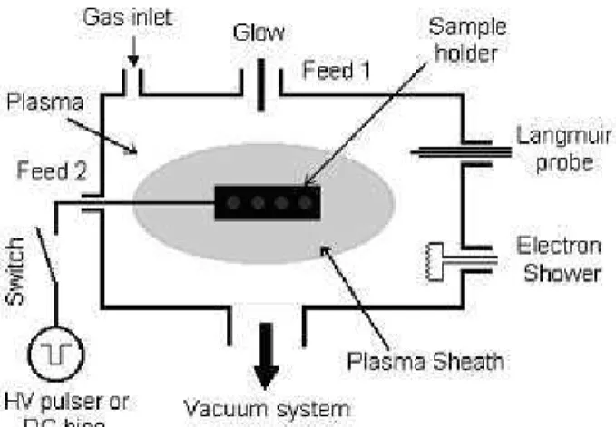
The schematic drawing of the experimental devices used for the hybrid processes are shown in Fig. 1. In this figure we show both: the case of hybrid process using alternated high pressure nitriding and low pressure DC PIII, in which we al-ternated the use of DC bias for the nitriding and biasing in Feed 2, and the case of hybrid process using PIII followed by nitriding, in which we alternated the HV pulser and DC bias in the Feed 2. Most components used for both processes are the same but in the first a high pressure discharge is tur-ned on to obtain a cathodic plasma on the sample support by feeding DC negative voltage (-600 to -800 V) through the power supply indicated by main glow (Feed 2), in Fig. 1. After reaching temperatures of 400 - 500oC, a low pressure diffuse plasma is generated in substitution to the cathodic plasma by driving a glow discharge through the feed 1 while maintaining a DC negative bias of 700V in the sample sup-port.
Figure 1. Schematic drawing of the experimental set-up for hybrid alternated high and low pressure nitriding and for PIII followed by low pressure nitriding processing of materials.
On the other hand, for the second hybrid process dis-cussed here, the feed 2 is used to drive the PIII treatment process while the glow discharge is run through the feed 1. For the subsequent nitriding, the DC bias is fed through feed
2 while the plasma is produced using the feed 1. Other com-ponents shown in the figures are common to both processes and have been discusses in previous papers [5].
The temperatures of the samples during the treatments (very critical for the first hybrid process) are carefully moni-tored using a RAYTEK infrared pyrometer, sensitive in the 200 - 2000◦C range.
For the measurement of x-ray diffraction (XRD) of nitri-ded SS304 and Ti6Al4V, Philips 3410 and PW3710 diffrac-tometers in the standard 2θmode were used.
For the AES (Auger Electron Spectroscopy) measure-ments used for determination of the elemental concentration in the samples, a spectrometer from FISONS Instruments Surface Science, model MICROLAB 310-F was used.
Tribological evaluations of the samples surface were conducted with a Tribo Scope nanomechanical indentation tester from Hysitron Inc.
Glow discharge optical spectroscopy (GDOS) depth pro-filing analysis was performed in a JY-5000RF (Jobin-Yvon) device.
Surface morphology of the Ti alloy samples was analy-zed by atomic force microsopy (AFM) operating the Shi-madzu SPM - 9500J3 nanoindenter in the dynamic mode.
3
Results and discussions
3.1
Part 1
Results on SS304 samples exposed to the first hybrid pro-cess, i.e. alternated high pressure nitriding and low pressure DC PIII will be discussed first. The discharge conditions were: for high pressure nitriding, the discharge was run at pressures of 30 - 40 Pa, -600 to -800 V and currents of 250 mA, while for low pressure nitriding, the discharge was run at8×10−2Pa, 900V, 80 mA, respectively. For the first cycle of the treatment, the plasma is produced using the sample support as the cathode. On the other hand, for the second cycle, the plasma is produced away from the sample support and it fills the chamber by self-diffusion while a bias vol-tage of -700 V is applied to the support to attract the ions. The working gas in this case was a mixture of nitrogen and hydrogen in the 1:1 ratio. These two cycles of 15 min each were repeated for 5 times, completing 150 min in total.
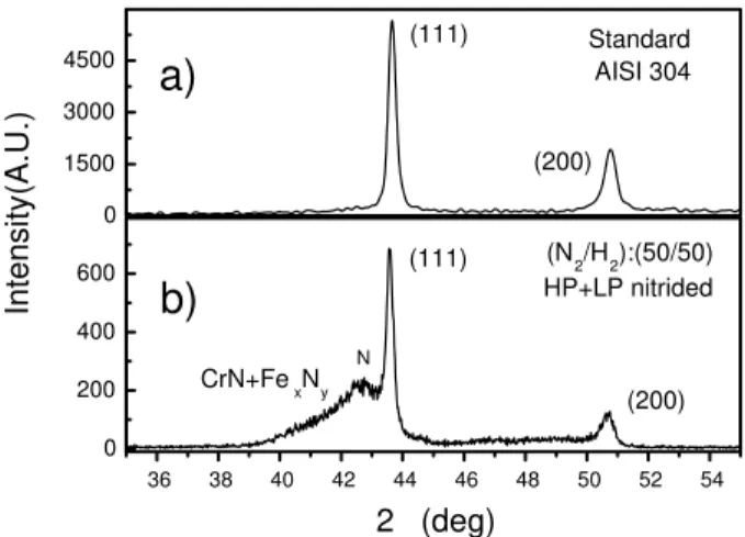
In Fig. 2(b) we show an XRD diffractogram obtained for SS304 treated by this hybrid process while in Fig. 2(a) a reference XRD for the standard SS304 sample is shown. A very prominentγNbroad peak can be seen to the left of nor-malγ(111) peak of Fe in Fig.2 (b), indicating a thick layer of theγN phase. This is the so called expanded austenite phase (or high concentration of nitrogen in solid solution) which presents excellent tribological properties as high hardness and resistance to wear. Indeed, the reached hardness in this case was 542 HV (an enhancement factor of2.7×,
compa-red to an untreated sample) which was confirmed by nanoin-dentation hardness profile, as shown in Fig. 3. The hardness profile obtained shows that near 150 nm the increase of hard-ness is about2.7×while even for 500 nm this factor is over 2.0×. In fact, at the depths lower than 100nm, the
could be due to a highly damaged surface (as was seen by glancing XRD results shown in a previous paper [13]).
36 38 40 42 44 46 48 50 52 54
0 200 400 600 0 1500 3000 4500
2 (deg)
Intensity(A.U.)
CrN+FexNy
N
(111)
(200)
b)
(N2/H2):(50/50) HP+LP nitrided (200)
(111)
a)
Standard AISI 304
Figure 2. Normal incidence XRD results for: (a) standard SS304; (b) (N2/H2): (50/50) gas mixture nitrided SS304.
0 100 200 300 400 500 600 700 800 4
6 8 10 12 14 16 18
20 SS 304 Hardness
Hardness (GPa)
Displacement into surface (nm)
HPN + LPN, 150min SS reference
Figure 3. Hardness profiles of standard SS304 sample and one tre-ated by hybrid high and low pressure nitriding processing.
The AES profiling obtained for this treatment can be seen in Fig. 4. Here we can see that the hybrid treatment enabled us to inject a huge amount of nitrogen into the Fe structure. More than 30% of the elements detected at 25 nm depth are nitrogen and even at 650 nm this percentage is over 20%. GDOS measurements (not shown here) con-firmed both glancing XRD[13] as well as AES results and indicated a nitrogen penetration of more than 2µm. Notice also that the amount of impurities introduced by this pro-cess is very low, concentrating them at the very surface of the samples (<10 nm).
0 100 200 300 400 500 600 700 0
10 20 30 40 50 60
SS 304 (N2/H2):(50/50) HPN + LPN
C
Ni Cr
O
N Fe
C N O Cr Fe Ni
CONCENTRATION (at.%)
DEPTH (nm)
Figure 4. AES profiles of SS304 treated under a plasma condition of (N2/H2) : (50/50) gas mixture, nitrided with alternating high
pressure and low pressure cycles.
3.2
Part 2
In this second part, we will discuss the results obtained by a hybrid process involving higher energy PIII (10 to 15 kV) combined with a low pressure nitriding, applied to SS304 and Ti6Al4V alloy.
Compact oxide layer on the surface of metal alloys is a strong barrier for the nitrogen diffusion into the bulk ma-terial. This prevents the effective use of ion nitriding in many types of metal alloys. PIII at moderated energy (10 - 30 keV) allows ion penetration depths deeper than these surface oxide layers. The damages caused by ion implanta-tion and the surface sputtering in these outermost layers may create favorable boundary conditions for an efficient subse-quent diffusive treatment such as ion nitriding.
We will start our discussion on results of this hybrid tre-atment applied to SS304. In a previous paper we have dis-cussed the formation of a double layer of expanded austenite
0 200 400 600 800 0
10 20 30 40 50 60 70
SS 304 N PIII treated
150min.
C N O Cr Fe Ni
CONCENTRATION (At.-%)
DEPTH (nm)
Figure 5(a). AES profiles of SS304 sample treated under a nitrogen plasma PIII for 150 min.
0 100 200 300 400 500 600
0 10 20 30 40 50 60 70
SS 304 N PIII (75min) combined with low pressure nitriding (75min)
C N O Cr Fe Ni
CONCENTRATION (At.-%)
DEPTH (nm)
Figure 5(b). AES profiles of SS304 sample treated under a nitro-gen plasma PIII (75 min) combined with low pressure ion nitriding (75 min).
In Fig. 5(a) we can see that a deep nitrogen penetration (800nm) was achieved by the PIII alone, applied for 150 min. This was due to a good thermal diffusion of the implan-ted nitrogen in SS304 at temperatures of 450◦C. The percen-tage of nitrogen introduced into the steel is typically 15%. Compared to that behavior, the result of Fig. 5(b) shows that a treatment with 75 min PIII followed by 75 min nitriding causes an increase of nitrogen percentage in the shallower regions. It reaches percentages over 20 % between 10 nm to 150 nm. This enriched nitrogen layer sits on top of the layer with about 10 % nitrogen concentration that extends over to 450 nm, which is the result of PIII treatment alone. This double layer in concentration reflects into double layer inγN phases. This kind of structures might be useful for some types of application where ability to support very high loads is required. Indeed, it was shown in a previous paper that the most adequate hardness profile (higher hardness to deeper depths and much higher hardness at the very surface) is obtained by using the hybrid process [9].
Next we will discuss the results obtained with this hybrid process (PIII followed by nitriding) applied to the Ti alloy. The effect of TiO2formed on the surface of the sample of this alloy may pose more difficulties for nitriding than in the case of the nitriding of steels. The thermal diffusion of nitro-gen in this alloy requires also much higher temperatures, of the order of 800oC. Hence an alternative nitrogen diffusion process would be welcome to enhance its surface properties when such high temperatures can not be obtained so easily. In the previous experiments, we had obtained enhancement in hardness (up to 70 %) and reduction of friction coefficient (down to 1/3) when we applied solely nitrogen PIII for up to 2 h, with pulsing voltages of 11 kV, 50µs duration and 400 Hz repetition frequency [14]. In the present experiment, PIII and nitriding were combined in the same way as in the case of SS304 treatment.
0 100 200 300 400 500
0 20 40 60
80 Ti6Al4V N PIII treated
150min C
N Ti V O Fe Al
CONCENTRATION (At.-%)
SPUTTERING TIME (s)
Figure 6(a). AES profiles of Ti6Al4V sample treated under a ni-trogen plasma PIII for 150 min.
0 100 200 300 400 500
0 20 40 60 80
Ti6Al4V N PIII (75min) combined with low pressure nitriding (75min)
C N Ti V O Fe Al
CONCENTRATION (At.-%)
SPUTTERING TIME (s)
Figure 6(b). AES profiles of Ti6Al4V sample treated under a nitro-gen plasma PIII (75 min) combined with low pressure ion nitriding (75 min).
75 min, an AES result as shown in Fig. 6(b) is obtained. Nitrogen uptake is not increased during the nitriding phase. Instead we notice some sputtering effect in that phase. In-deed, when we increased the nitriding time to 4h, the initi-ally nitrogen implanted layer was all sputtered away. AFM photos (not shown here) revealed that the Ti6Al4V sample with result of Fig.6 (b) had a much smoother surface than sample of Fig.6(a).
The nanoindentation measurements for these two pro-cesses showed hardness profile as shown in Fig. 7. Here we also included the data for PIII and 4h nitriding. We can see a hardness improvement of about 50% for all the treat-ments under discussion. This independence of hardness va-lues with nitrogen implanted profile is a well known effect in the field of ion implantation, the cause of this improvement being attributed to some damages and dislocations occurring in front of the implanted layer.
0 200 400 600 800 1000 1200 2
3 4 5 6 7 8 9 10
Hardness (GPa)
Displacement into surface (nm)
TAV (Ti 6Al 4V) Standard only PIII PIII + 4 h nitriding PIII + 75 min nitriding
Figure 7. Hardness profiles of standard Ti6Al4V sample, one trea-ted by PIII alone, one treatrea-ted by PIII combined with nitriding (75 min) and one treated by PIII and nitriding (4 h).
We expect that the smoother surface of Ti alloy obtained by the hybrid PIII combined with nitriding process leads to a much lower friction coefficient due to its smoother surface. Unfortunately the hardness increase seems to be saturated at 75 min nitriding condition. A PIII treatment at higher temperatures (of order of 800◦C) should increase the trea-ted layer thickness and when combined with nitriding may produce a final surface with lower friction coefficient.
4
Conclusion
Two hybrid material processing methods were developed. In one of them, ion nitriding of SS 304 at high pressure was combined with a low pressure nitrogen DC PIII and applied to take advantages of high temperature (near 450oC) achie-ved in the high pressure phase and of effective ion accele-ration and deeper implantation by the bombardment of ions with energies near 0.7 keV at the low pressure phase. This treatment led to a very efficient ion implantation and diffu-sion of nitrogen (about 2µm penetration) in SS 304 and as
a result, formation of a thick layer withγN phase with im-proved hardness (factor of2.7×over the reference sample)
and low surface contamination.
In the second experiment, hybrid treatment combining nitrogen PIII and subsequent nitriding was attempted in two different materials (SS 304 and Ti6Al4V). Although a deep treatment was not achieved by this process, as suggested by previous paper on results of ion beam combined with nitri-ding processing[11], we obtained a few new results in sur-face modification by plasma and PIII ion implantation. For SS 304, a double layer with differentγN’s (γN1 andγN2) were obtained, according to XRD diffraction and AES filing results. A double layer with a very high hardness pro-file at the very surface obtained by nitriding and a deep layer with moderate hardness obtained by PIII, could lead to a new material surface with high strength capable of suppor-ting high load.
In the case of Ti6Al4V sample exposed to this method of hybrid surface modification, it was found that PIII alone pro-duces sample with a shallow implanted layer (about 65 nm) with high hardness, the surface of which is sputtered quite strongly during subsequent ion nitriding. Little uptake of ni-trogen occurs during this nitriding phase but a smoothening of the surface results which can reduce the friction coeffici-ent. Hence a new attempt will be made combining a high temperature PIII with ion nitriding finishing which could result in a thick, high hardness and low friction Ti6Al4V surface, much desired in the industrial applications of this material.
Acknowledgements
We thank to FAPESP and CNPq for financial support. Two of us, GFG and KGK thank to FAPESP for research grants.
References
[1] In Plasma Science and Technologyby Herman V. Boenig, Cornell University Press, Ithaca and London, 1982.
[2] B. Larish, U. Brusky, and H. J. Spies. Surf. Coat. Techn. 116-119, 205 (1999).
[3] InSurface Modification Engineering, Vol.II, Ed. Ram Kos-sovsky, CRC Press Inc., Florida, 1989.
[4] InHandbook of Plasma Immersion Ion Implantation and
De-position, Ed. Andr´e Anders, J. Wiley&Sons Inc., 1st ed.,
To-ronto, 2000.
[5] M. Ueda, L. A. Berni, G. F. Gomes, A. F. Beloto, E. Abramof, and H. Reuther. J. Appl. Phys.86, 4821 (1999).
[6] W. Ensinger, K. Voltz, and B. Enders, Surf. Coat. Techn. 120-121, 343 (1999).
[7] M. Ueda, G. F. Gomes, E. Abramof, and H. Reuther, Nucl. Instrum. Meth. B206, 749 (2003).
[9] K. Kostov, M. Ueda, M. Lepienski, P. C. Soares Jr, G. F. Gomes, M. M. Silva, and H. Reuther, Surf. Coat. Technol.
186/1-2, 204 (2004).
[10] I. Kanno, K. Nomoto, S. Nishijima, T. Nishiura, and T. Okada, Nucl. Instrum. Meth. B59-60, 920 (1991).
[11] N. Nunogaki, H. Suezawa, Y. Kuratomi, and Y. Miyazaki, Vacuum39, 281 (1989).
[12] S. Y. Wang, P. K. Chu, B. Y. Tang, X. C. Zeng, Y. B. Chen, and X. F. Wang, Surf. Coat. Technol.93, 309 (1997).
[13] M. Ueda, G. F. Gomes, E. Abramof, and H. Reuther, Surf. Coat. Technol.186/1-2, 291 (2004).