Abstract— This paper proposes a new design of Planar Inverted-F Antenna with complementary split ring resonators (CSRRs). The operating frequency of this antenna is 2.425 GHz for Wireless Local Area Network (WLAN) application. The method is to incorporate a single CSRR cell and a periodic array CSRRs on the radiating patch. We studied the effect of this method on the characteristics of antenna in free space and in the presence of the user. We used a homogeneous model of a human head near our antenna. The parameters that considered in these works are gain, electric field, magnetic field, return loss, radiation pattern, power loss density and Specific Absorption Rate. The addition of CSRRs on to PIFA antenna will improve the gain from 4.76 dB to 4.81 dB and will reduce the Specific Absorption Rate from 3.57 W/kg to 2.95 W/kg.
Index Terms— Complementary Split ring resonators, Gain, Specific Absorption Rate, Wireless Local Area Network.
I. INTRODUCTION
Wireless communications have progressed very rapidly in recent years, and researchers began working on miniaturization and improved antennas and reduce the value of the specific absorption rate . The EM absorption in the human head from the radiated antenna on a mobile phone is measured in terms of the specific absorption rate (SAR), which is defined as the power absorbed by a unit mass of body tissue [1]. The mass measured for SAR evaluation corresponds to a mass of 1 g or a mass of 10 g of body tissue. Various techniques have been discussed in the last decade to reduce of the Specific Absorption Rate (SAR) of cellular phone. Kusuma AH, et al [2] was proposed, a novel structure of PIFA with an additional thin metal shim-layer in between the patch and the chassis with conducting sidewalls attached at the free-sides of the antenna. Il Kwak S, et al was used [3], a two patch EBG structure as an additional antenna element. Faruque MRI, et al [4] was used, a triangular-shaped split ring resonator (SRR) surface in between the PIFA and the human head to reduce the SAR at GSM 900 MHz. To meet the miniaturization requirement, the antennas employed in mobile terminals must have their dimensions reduced accordingly. The methods of improvement and miniaturization of antennas have appeared ago the evolution of communications technology [5]. In the literature, these methods are divided into three classes. The first class is devoted to the methods that
Effect of Complementary Split Ring
Resonator
Structure on PIFA Antenna
Nizar Sghaier1, Lassaad Latrach1 and Ali Gharsallah11
Unit of Research Circuits and Electronics Systems HF, Faculty of Science, departement Electronics
use the geometry of the radiating element as the geometry fractal and refolding[6-7].The second class includes methods that use the concept of high permittivity substrates [8]. In the third class, includes methods that use metamaterials that can be metallic metamaterials or complementary metamaterials. In this paper, a new approach of a complementary split ring resonator (CSRR) PIFA antenna is introduced to reduce the SAR in the human head and the size of PIFA antenna. This manuscript is divided into three parts, the first part is devoted to the presentation of the antenna characteristics. The second part is specified to describe the influence of CSRRs on antenna parameters[9-10]. And we finished with a demonstration to confirm our results.
II. PIFAANTENNAWITHOUTCOMPLEMENTARYSPLITRINGRESONATORS
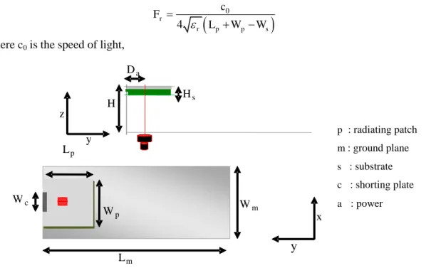
The PIFA antenna studied, Figure 1 is composed by a rectangular radiating patch witch length is
Lp = 10 mm and width Wp = 16 mm. The patch is placed at a height h from the ground plane. The last
has a length Lm = 100 mm and a width Wm = 40 mm. The patch is matched to the ground plan via a
rectangular shorting plate. The shorting plate has a width Wc = 0.5 mm and a length Lc = H = 8 mm.
The patch is integrated on a dielectric substrate such FR-4 having a relative constant dielectric εr equal
to 4.3, a relative permeability μr equal to 1, a loss tangent tanδ equal to 0.0018 (cont.fit) and a
thickness Hs equal to 1.2 mm. The PIFA antenna is fed by a coaxial cable of excitation having a
characteristic impedance Zc equal to 50 Ω. The distance between the power supply and the shorting
plate is Da = 5mm.
The geometric parameters of the patch antenna, shown in Figure 1 are determined from the following equations [10]:
0
4
r
r p p s
c F
L W W
(1)
where c0 is the speed of light,
Fig. 1. Parameters geometric of PIFA antenna.
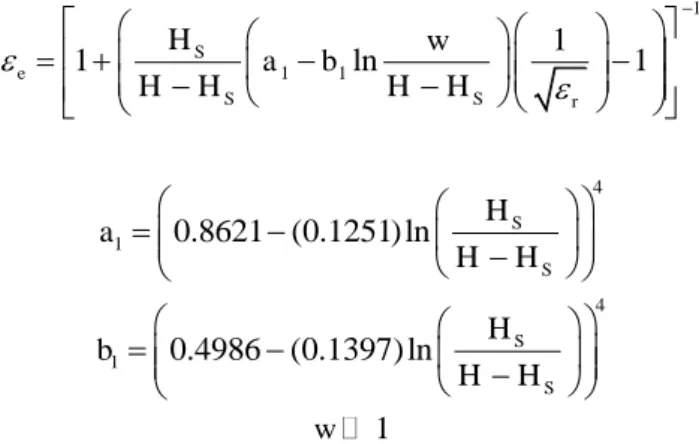
The effective permittivity:
L m
H s
x
y
y
z
W p
D a
W c W
m
H
p : P atch rayonnant
s : S ubstrat
m : P lan de masse
c : C ourt - circuit
a : A limentation
L p
1
1 1
1
1 S ln 1
e
S S r
H w
a b
H H H H
(2) where
:
41 0.8621 (0.1251) ln S S H a H H
(3)
4
1 0.4986 (0.1397) ln S S H b H H
(4)
1
w (5)
III. RESULTSANDDISCUSSION
Figure 2 shows the fabricated PIFA antenna.
Fig. 2. Photograph of the realized PIFA antenna.
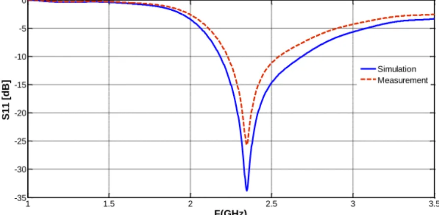
The measured and simulated S11 of the proposed antenna are simultaneously illustrated in Fig. 3. It
is clearly seen that the measured and computed S11 are in excellent agreement with each. Such an
excellent agreement between measured and simulated results indicates the high tolerance of this antenna in terms of dimensions and materials.
From the measured results, we note that our PIFA antenna having a resonant frequency equal to 2.425 GHz with a return loss S11 equal to -25.15 dB and a frequency band Bf equal to 529 MHz
measured at -10 dB.
1.5 2 2.5 3 3.5
-30 -25 -20 -15 -10 -5 0 F[Ghz] S 1 1 [d B ] Measurement Simulation
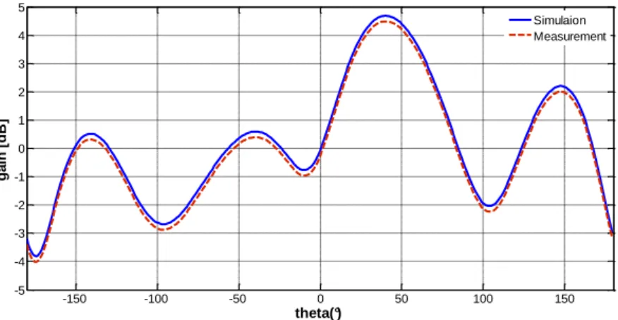
Figure 4 indicates the measured and simulated gain versus θ at one selected frequencies, 2.425 GHz. Thus, the reference antenna is characterized by a gain equal to 4 dB measured at 2.425 GHz.
-150 -100 -50 0 50 100 150
-4 -3 -2 -1 0 1 2 3 4 5
theta(°)
g
a
in
[
d
B
]
Simulation measurement
Fig. 4. Radiation pattern of PIFA Antenna, to calculate the gain
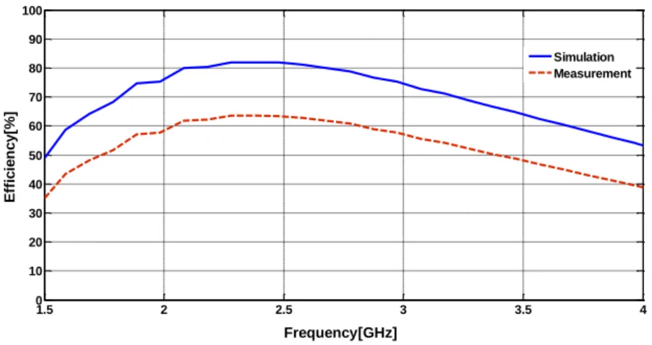
Figure 5 shows the measured and simulated antenna efficiency of the antenna versus frequency for the proposed PIFA antenna.
1.5 2 2.5 3 3.5 4
0 10 20 30 40 50 60 70 80 90 100
Frequency[GHz]
E
ff
ic
ie
n
c
y
[%
]
Simulation Measurement
Fig. 5. Radiation pattern of PIFA Antenna, to calculate the efficiency.
IV. PIFAANTENNAWITHCOMPLEMENTARYSPLITRINGRESONATORS
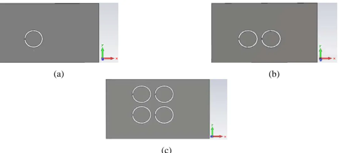
The study of the integration of complementary metamaterials with PIFA [11] antenna is based on two interesting parts: the first is devoted to use one additional element of a complementary split ring resonator having a fixed position in the middle of the radiating patch The objective of is to extract the best results. The second part is the extension of the previous study, the complementary metamaterials used are presented by a homogeneous and periodic array of split ring resonators. This array has the same position as the reference case of the PIFA antenna found in the previous section.
(a) (b)
(c)
Fig. 6. PIFA antenna with present the CSRR: (a) inclusion of one cell CSRR, (b) inclusion of two CSRR and(c) inclusion of four elements of CSRR
V. RESULTSANDDISCUSSION
The simulation results collected by the CST Microwave Studio software is stored in Table 1 on the comparison of the characteristic parameters of patch antenna in the absence and presence metamaterials.
TABLE.1RESULT OF VARIOUS PERFORMANCE PARAMETERS OF THE PIFA ANTENNA IN THE PRESENCE OF CSRR. Structure fr (GHz) S11 (dB) Gain (dB) Emax (V/m) Imax (A/m) Efficiency (%)
PIFA 2.425 -25.15 4 3289 21.2 81.2
PIFA +1CSRR 2.35 -33.69 5.09 3989 31.2 94.2
PIFA +2CSRR 2.34 -32.05 5.02 4676 46.2 82.4
PIFA +4CSRR 2.33 -31.81 4.24 4888 46.3 75.2
we note:
fr (GHz): Resonant Frequency
S11(dB): Return Loss
Emax (V/m): Hight Value of the electric field
Imax (A/m): Hight Value of the magnetic field
The number of cells is limited by the return loss of the antenna. Indeed, when we used six cells the value of S11 becomes equal to -12 dB. From the simulation results we noticed at firstly moment the
number of CSRR elements is inversely proportional to the resonant frequency, as indicated by the variation curve of the return loss shown in Fig .7.
1 1.5 2 2.5 3 3.5
-35 -30 -25 -20 -15 -10 -5 0
F(GHz)
S
1
1
[
d
B
] 1 CSRR
2 CSRRs 4 CSRRs
We have noticed that adding SCRR cell reduces the resonant frequency and therefore the patch size reduction. Consequently, we observe clearly that excites a significant improvement between the one element of the CSRR course at remarkable values of return loss, gain, directivity and distributions of the electromagnetic field and the surface current of the antenna.
VI. MEASUREMENTRESULTS
Figure 8 shows the fabricated PIFA antenna to use one additional element of a complementary split ring resonator. Considering the simple manufacturing facilities in our lab CSRR PIFA antenna, the structure is successfully constructed and measured.
Fig. 8. Photograph of the realized CSRR PIFA antenna.
The measured and simulated S11, gain and efficiency of the CSRR PIFA antenna are simultaneously
illustrated in Fig. 9, 10, and 11. It is clearly seen that the measured and computed results are in excellent agreement with each. Such an excellent agreement between measured and simulated results indicates the high tolerance of this antenna in terms of dimensions and materials.
1 1.5 2 2.5 3 3.5
-35 -30 -25 -20 -15 -10 -5 0
F(GHz)
S
1
1
[
d
B
]
Simulation Measurement
-150 -100 -50 0 50 100 150 -5 -4 -3 -2 -1 0 1 2 3 4 5 theta(°) g a in [ d B ] Simulaion Measurement
Fig. 10.Radiation pattern of CSRR PIFA Antenna, to calculate the gain.
1.5 2 2.5 3 3.5 4
45 50 55 60 65 70 75 80 85 90 95 F(GHz) E ff ic ie n c y [% ] Simulaion Measured
Fig. 11.Radiation pattern of PIFA Antenna, to calculate the efficiency.
VII. DEMONSTRATION
A. Power loss Density
Principally the amplitudes of electric and magnetic fields radiated directly affect on the density of the total radiated power p(r, θ, ) of the antenna [12]. This radiated power is defined by the following equation:
2
, , ray ray ray
m
E
p r E H
Z
(6) where:
ray
d A
E grad V
dt
(7) 1
ray
H rot A
(8)
ray m ray E Z H
(9)
p(r, θ, ) is maximum in the case of the patch antenna with an elementary CSRR designed to validate and authenticate our approach. For this reason we offer Table 2 of measures the electromagnetic field radiated and total radiated power density for different structures the patch antenna in the absence and presence of complementary metamaterials.
TABLE.2MEASUREMENTS THE ELECTROMAGNETIC FIELD AND THE TOTAL RADIATED POWER DENSITY. Structure Eray
(V/m)
Hray (A/m)
Zm (Ω)
p(r, θ, ) (mW/m2)
PIFA 9.4 0.025 376 235
PIFA +1CSRR 11.7 0.0311 376.2 363
PIFA +2CSRR 9. 38 0.0249 376.7 233
PIFA +4CSRR 8.52 0.0226 377 192
According to the results shown in the above table, we can show that the highest amplitudes of electric and magnetic fields radiated and total radiated power density are obtained for the metamaterials antenna structure which is composed of a PIFA antenna and a one complementary element of a split ring resonator. The latter structure allows us to amplify the total radiated power density to reach 363 mW/m2 by an increase equal to 128 mW/m2 than the PIFA antenna setting alone. Conversely, the technique of association of a unit cell CSRR with patch antenna is more efficient than the integration of a array CSRRs where the total radiated power density is reduced to 192 mW/m2 by a degradation equal to 43 mW/m2 compared to the reference case. The radiated power density for different structures is shown in Fig. 12.
(a) (b)
(c) (d)
B. The specific Absorption Rate
The human head is represented by a homogeneous sphere of diameter equal to 200 mm and located at a distance equal to 10 mm of the antenna. The relative permittivity and electric conductivity of the human head tissues is achieved using Gabriel S. et al [13]. With the operating frequency of our antenna, the relative permittivity equal to 38.2 and the electric conductivity equal to 1.68 [S/m]. The sphere having a volume element of giving density ρ equal to 1000.
The Specific Absorption Rate (SAR) is a defined parameter for evaluating the power absorbed in human tissue. It is given by equation (10):
2
SAR E 2 (10)
The Specific Absorption Rate (SAR) for with and without CSRR is presented successively in the following figures:
(a) (b)
(c) (d)
Fig. 13. The specific absorption rate: (a) without CSRR, (b) with one CSRR, (c) with two CSRR, (d) with four CSRR.
The maximum 10 g averaged SAR of the basic antenna structure and antenna with the proposed four CSRR structure is 3.57 W/kg and 2.95 W/kg at 2.425 GHz.
The simulation results are shown goods. In adding of CSRR decrease the electric field which ensures a reduction in SAR.
VIII. CONCLUSION
efficiencies, gains and Power loss density. Moreover, the SAR results indicate significant reduction in the SAR values at the upper frequency band. Furthermore, future studies may be extended to develop metamaterial CSRR, which to apply this method in the multi-band antennas.
ACKNOWLEDGMENT
I would like to express my deepest thanks to Dr. Ali Gharsallah, my thesis Director.
REFERENCES
[1] Hossain MI, Faruque MRI, Islam MT. Analysis on the effect of the distances and inclination angles between human head and mobile phone on SAR. Progress in biophysics and molecular biology 119, no. 2, 103–110 doi: 10.1016 /j. pbiomolbio .2015.03.008. pmid:25863147, 2015.
[2] Kusuma AH, Sheta A-F, Elshafiey IM, Siddiqui Z, Alkanhal MA, Aldosari S, et al. A new low SAR antenna structure for wireless handset applications. Prog Electromagn Res;112: 23–40. doi: 10.2528/pier10101802, 2011
[3] Il Kwak S, Sim D-U, Kwon JH, Do Choi H. Comparison of the SAR in the human head using the EBG structures applied to a mobile handset. Microwave Conference, 2007 European. IEEE;. pp. 937–940, 2007.
[4] Hossain MI,Islam MT. Design of Miniaturized Double-Negative Material for Specific Absorption Rate Reduction in Human Head. PloS One.;9: e109947. doi: 10.1371/journal.pone.0109947. pmid:25350398, 2014.
[5] S. R. Best, "On the Performance Properties of the Koch Fractal and Other Bent Wire Monopoles", IEEE Transaction on Antenna and Propagation,p.1292, Vol. 51, No 6, June 2004.
[6] N. A. Saidatul, A. A. H. Azremi, R. B. Ahmad, P. J. Soh and F. Malek, ‘’multiband fractal planar inverted f antenna (f
-pifa) for mobile phone application’’, Progress In Electromagnetics Research B, Vol. 14, 127–148, 2009.
[7] Seif Naoui, Lassaad Latrach, and Ali Gharsallah, “Metamaterials Dipole Antenna by Using Split Ring Resonators for RFID
Technology”, Microwave and Optical Technology Letters, Vol.56: pp.2899–2903, 2014; DOI 10.1002/mop.28731.
[8] W.-J. Liao, T.-M. Liu and S.-Y. Ho, “Miniaturized PIFA Antenna for 2.4 GHz ISM Band Applications,” IEEE Proceedings of the 6th European Conference on Antennas and Propagation (EUCAP), Prague, 26-30, pp. 3034-3037n, March 2012.
[9] Gil, I. ; Fernandez-Garcia, R. "Analysis of PIFA antenna coupling in nearby traces and reduction with CSRRs in PCB at 2.45 GHz" Electromagnetic Compatibility (EMC), 2015 IEEE International Symposium on, Page(s): 361 - 365.
[10]S. C. Basaran and E. Dokuzlar, " A Frequency Reconfigurable PIFA Design for Wireless Communication Applications" PIERS Proceedings, Prague, Czech Republic, July 6{9, 2015, pages 118-121.
[11]Loutridis, A. John, M. & Ammann, M.J. “Dual Band LTE Planar Inverted-F Antnna for M2M Applications”, Microwave and Optical Technology Letters, vol. 55, issue 12, pp. 2925–2929, DOI: 10.1002/mop.27980, 2013.
[12]Gabriel, S., R.W. Lau and C. Gabriel, 1996. The dielectric properties of biological tissues: III. Parametric models for the dielectric spectrum of tissues. Phys. Med. Biol., 41: 2271-2293. DOI: 10.1088/0031-9155/41/11/003