!"#$% "&# ' ( )
* + , - .
!!/%0 "## - . -. ( )
!
"
!
# $
%
&
"
'' "
The displacement of a fluid by liquid injection occurs in some practical applications like oil recovery in porous media and cementation of drilling wells. The dimensionless numbers that govern this problem are the capillary number, Reynolds number and viscosity ratio. An overview of selected oil recovery processes shows that hydrolyzed polyacrilamide and bio-polymers, as xanthan gun, are commonly pumped into oil reservoir in order to aid oil recovery. These materials are non-Newtonian, presenting high viscoelastic effects. The fractional mass deposited on the tube wall and the shape of the interface on liquid-liquid displacement of two Newtonian materials was studied previously by Soares et al. (2005). The goal of the present work is to conduct an experimental investigation analyzing viscoelastic effects on the fractional coverage and on the shape of the interface for both: a polymer displacing a Newtonian liquid and a Newtonian liquid displacing a polymer.
Keywords: liquid-liquid displacement, capillary tubes, viscoelastic materials, oil recovery
Introduction
1The present work deals with the experimental analysis of the displacement of a fluid in the interior of a capillary tube by the injection of another fluid, which is immiscible with the first. Practical applications include the cementation process of production and injection wells and the flow through porous media during enhanced oil recovery. Typically, oil recovery simulators represent the porous medium by a net of interconnected capillary tubes. This network approach, that has been investigated by a number of authors as discussed by Stark and Manga (2000), represents a quite good approximation of the porous medium, while a single straight tube geometry is obviously a rather simplification of the true porous media geometry. However, the investigation of interfacial tension effects, viscosity ratio and rheological properties can be done accurately in a single straight tube and provide insights for a more realistic pore-structure flows. An accurate analysis on the liquid-liquid displacement in capillary tubes consist in determine the configuration of the interface between the two liquids and, consequently, the amount of liquid that is left behind adjacent to the wall. This analysis depends on investigation of capillary and Reynolds number and viscosity ratio.
An overview of selected oil recovery processes shows that hydrolyzed polyacrilamide and bio-polymers, as xanthan gun, are commonly pumped into oil reservoir in order to aid oil recovery by providing mobility control to the injection water, as extensively discussed in the articles of Dreher and Gogarty (1979), Johansen (1979) and Khagram, Gupta and Sridhar (1985). These materials are non-Newtonian, presenting high viscoelastic behavior. Hence, the analysis of these properties is, in fact, together with capillary number and viscosity ratio, quite important and can contribute for a better comprehension of oil recovery processes.
The majority of the related work found in the literature deals with the case of a gas displacing a viscous liquid, going back to the pioneer work of Fairbrother and Stubbs (1935) and Taylor (1960). In the experiments reported in these early papers, the Reynolds number was kept small enough to assure negligible inertial effects. The main goal was to determine the fraction of mass deposited on the tube wall, m, which, with the aid of the mass conservation principle, can be written as a function of the velocity of the tip of the
Paper accepted February, 2008. Technical Editor: Monica Feijó Naccache.
interface, U, and the mean velocity of the liquid ahead of the liquid-liquid interface, as shown in Eq. (1).
U u U
m= − (1)
Taylor (1960) studied the dependence of the mass fraction on the capillary numberCa=µU/σ, where µ and σ are the liquid viscosity and surface tension, respectively. His analysis indicated that the amount of liquid deposited on the wall rises with the interface speed, and that m tends asymptotically to a value of 0.56 as Ca approaches 2. Working on the same problem, Cox (1962) studied the mass fraction over a wider range of the capillary number, and also observed that m reaches an asymptotic value at high capillary number. However, he showed that this asymptotic value was 0.60 as Ca approached 10. Using the lubrication approximation, Bretherton (1960) derived a theoretical correlation between the mass fraction and the capillary number, and the agreement between his predictions and Cox's experiments is good in the range of 3 2
10
10− ≤Ca≤ − . Gas-displacement of non-Newtonian liquids has also been investigated by a number of authors. Comprehensive reviews on this subject are reported by Soares et al. (2006) (see references therein).
Articles dealing with the analysis of liquid-liquid displacement in capillary tubes are much scarcer. One of these few papers is given by Goldsmith and Mason (1963) who report experimental results on the amount of displaced liquid left on the tube wall as a function of different parameters when two Newtonian liquids are used. In their experiments, the displacing material is a long drop of a viscous liquid. The results showed that the mass fraction rises as the viscosity ratio Nµ=µ2/µ1 is decreased, where the index 1 refers to
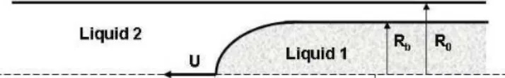
The visualization of the tip of the interface in this process enables the determination of the configuration of the interface and the amount of liquid attached to the wall. Figure 1 shows a sketch of the liquid-liquid interface, where R0 is the tube radius and Rb the
radius of the cylindrical portion of the interface. Both liquids, the displacing and displaced, can be a polymer solution presenting viscoelastic behavior.
Nomenclature
0
R = radius of the capillary tube, m
b
R = radius of the cylindrical portion of the interface, m
0
D = external diameter of capillary tube used, m
b
D = internal diameter of capillary tube, m U = velocity of the tip of the interface, m/s
u = mean velocity of the liquid ahead of the interface, m/s m = fraction of mass deposited on the tube wall, dimensionless Ca = Capillary number, ηU/σ dimensionless
η
N = Viscosity ratio, η1/η2 dimensionless
Greek Symbols
ρ = density, kg/m3
µ = viscosity, Pa.s
σ = surface tension, N.m
γ
= shear rate, s-1ε
= extensional rate, s-1s
η = shear viscosity, Pa.s
u
η = extensional viscosity, Pa.s
0
η = shear viscosity at zero shear rate, Pa.s
1
Ψ = first normal stress difference, Pa
Material Characterizations
The selection of the liquids to the experiments was rather difficult. The pair of liquids used had to be immiscible and with refractive indexes sufficiently different from each other in order to render a visible interface. In addiction, to eliminate inertial effects, the viscosity of each material must be high enough. Furthermore, the densities had to be as close as possible to minimize buoyancy effects, as discussed by Soares et al. (2005).
All the experiments were performed using a sample of materials composed by two Newtonian liquids and two viscoelastic polymeric solutions. The first Newtonian liquid used was a soybean oil. Its density was ρ=915Kg/m3 and its viscosity
Pa.s 10 x 50 −3
=
µ . The
second one was a solution of polyethylene glycol (PEG, MW=6000 g/mol) in water. The viscosity level could be achieved by changing the polymer concentration and by using a concentration of 20% of PEG, the measured viscosity wasµ=27x10−3Pa.s. The density of the
was a solution composed by 30%, in weight, of PEG and 0.21% of PEO. The densities of the PEG-PEO aqueous solution was respectively ρ=1031Kg/m3 and 3
Kg/m 8 . 1052
=
ρ for Polymer-A and
Polymer-B.
The interfacial tension for each pair of liquids was measured by carefully placing a layer of the lighter liquid at the top of the surface of the heavier liquid, previously placed in a beaker, and then using a Lauda Ring Tensiometer to determine the interfacial tension. Table 1 shows the interfacial tensions for each liquid with respect to soil bean oil. The surface tension for the aqueous solutions with 20% of PEG was σ =18.75x10⁻³Nm and for the more concentrated solution, with 30% of PEG, was obtained σ=18.27x10⁻³Nm.
Table 1 Material compositions and physical properties. Here, σ is the interfacial tension referent to Newtonian liquid and η0 is the zero shear rate viscosity.
Material
% PEG
%
PEO kg/m3 ρ
10-3Pa.s
0
η 10
-3Nm σ
Soybean --- --- 915.0 50.00 --- PEG-water 20 0.0 1030.0 27.47 18.75 Polymer-A 20 0.1 1031.0 27.50 18.75 Polymer-B 30 0.21 1052.8 110.00 18.27
Viscometric Measurements
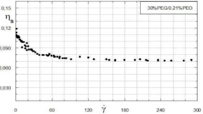
The rotating rheometer UDS 200 from Paar Physica with the cone-plate geometry was used to measure the viscometric material functions. Figure 2 shows the dependence of shear viscosity, ηson the shear-rate,
γ
, for Polymer-B. This sample exhibits a shear-thinning behavior in the range of 0≤γ≤100, reaching a Newtonianplateau of 3
10 75 −
= x
η for γ≤100. For Polymer-A, the measured data indicates a constant shear viscosity, namelyη=27x10−3, for the entire range of rate imputed. As indicated by the tests, the shear-thinning behavior of Polymer-B is attributed to its high concentration of oxide of polyethylene. Figure 3 shows the first normal stress coefficient,Ψ1, as a function of shear-rate for
Polymer-B. The test suggests a constant level of Ψ1 close to 0.1 Pa/m2 for γ≤10 and, forγ≥10,
1
Figure 2. Shear viscovity vs shear rate for Polymer B.
Figure 3. First Normal Stress Difference vs shear rate for the Polymer B.
Extensional Measurements
Tests on extensional viscosity for the polymeric samples used on the experiments were carried out with the RFX extensiometer from Rheometric Scientific. This apparatus uses a suction device to supply the stretching force necessary for extending the solution. The extensional flow occurs between two aligned opposite tubes. Figures 4 and 5 show the extensional viscosity,ηu, as a function of the extensional deformation rate,
ε
, for Polymer-A and Polymer-B respectively. As it can be seen, they exhibit a high extensional thickening behavior.Figure 4. Extensional viscosity vs extensional rate for Polymer A.
Figure 5. Extensional viscosity vs extensional rate for Polymer B.
Hence, while, the first normal shear stress decreases significantly with the increase of deformation rate, the extensional viscosity becomes the most important non-Newtonian property because of its extensional-thickening behavior. In oil recovery is quite common to occur processes in which the extensional viscosity is the dominant rheological property, Khagran et al. (1985).
Experiments
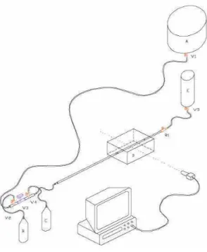
The experimental apparatus used in the present work, sketched in Fig. 6, was the same one used for the experimental analysis presented in Soares et al. (2005). Initially, the displacing liquid (Liquid 1) is stored in reservoir (A), and the displaced liquid (Liquid 2), in reservoir (E). Collecting Tanks (B) and (C) are auxiliary tanks used in the process of eliminating air bubbles in the system, as explained in Soares et al. (2005). The flow was controlled by cut-off valves (V1 to V5) and by the gate valve R1. The glass capillary tube was L = 1.5m long, and the inner and outer diameters were D0 =
5mm and Dext = 7mm, respectively. The tube was mounted inside a
plexiglas box (D) filled with glycerin in order to minimize distortions of the interface image. A CCD camera mounted at right angle to the side wall of the plexiglas box was used to get the image of the interface as it traveled through the glass capillary. The camera was connected to a VCR to record the images.
Figure 6. Experimental apparatus.
Figure 7. Representative image of the interface.
Since the liquids had different viscosities, the pressure loss along the capillary changes as Liquid 1 takes over the tube. This change in pressure loss can lead to a change in the drop speed as it travels through the capillary. However, this problem can be minimized by assuring that most of the overall pressure loss occurs in the gate-valve, so that the pressure loss along the capillary is always negligible. Therefore, any variation that occurs in the later causes no appreciable change in the overall pressure loss of the system, and thus the interface always travels with constant speed. The interface velocity U is measured by recording the time that it takes to travel between two axial positions marked on the tube. The maximum interface velocity that could be measured with accuracy was of about 0.15m/s, which determined the maximum capillary number hat could be obtained in the experiments. Besides that, when the capillary number was approximately Ca = 0.5 the flow become unstable and the long drop begins to collapse in small ones, limiting, again, the range of capillary number explored. After each run, the tube is rigorously cleaned to remove all contaminants. This procedure is necessary to avoid changes in surface tension.
U u U D D
m= − b = −
0
1 (2)
It is important to notice that, in the particular case of a rather low-viscosity displacing fluid, as in gas-displacement, the average velocity U is also equal to the interface velocity, i.e.,U=U.
Therefore, only in this limiting case (viz., as →∞
2 1 η
η ), the mass
fraction m can be evaluated via the expression employed by Taylor (1960), namely, Eq. (1).
The experimental data were obtained for Reynolds numbers small enough to assure negligible inertial effects. A representative image of the interface can be seen on Fig. 7. The main goal was to study the displacement of polymeric liquids exhibiting viscoelastic properties as both displacing and displaced liquid. As in the previous work of Soares et al. (2005), the fractional mass, m, was calculated using the diameters of the tube and the drop. The capillary number, Ca, and viscosity ratio,Nη, were defined as a
function of the zero-shear-rate viscosity,
0 η .
Figure 8 compares two materials used in the recovery of a Newtonian liquid (Soil Bean Oil). The first is a Newtonian liquid (PEG-Water solution) and the second is a viscoelastic solution, namely here Polymer-A. As usually, this comparison is shown in terms of the fractional deposited mass, m, as a function of the capillary number, Ca, for a fixed viscosity ration, namely =1.8
η
N .
The white dots correspond the liquid-liquid displacement of the two Newtonian materials while the blacks are for Polymer-A as displacing material. The capillary number analyzed was limited to the range of 0≤Ca≤0.3. This limitation was determined by the maximum bubble velocity, U, possible to be captured by the CCD camera used on the experiments. Furthermore, the bubbles tend to collapse at capillary numbers close to 0.5. This is an additional limitation for the analysis presented by this work. Figure 8 suggests a capillary dominated process for 0≤Ca≤0.2 and no viscoelastic effects can be observed. Although, when the capillary number approaches 0.2 the fractional mass, m, tends to an asymptotic value of 0.46 when Polymer-A is the displacing liquid. On the other hand, the results suggest that m increases continuously when the displacing liquid is another Newtonian material. The viscoelastic effects must be more pronounced for more concentrated polymer solutions, reducing the range of capillary number where the capillary forces dominate the process. Clarifying the previous analysis Fig. 9 shows images of the tip of the liquid-liquid interface for two capillary numbers, Ca=0.198; 0.255, at the same fixed viscosity ratioNη=1.8. Images on the left are for the two Newtonian
Figure 8. Fractional mass as a function of capillary number at fixed viscosity ratioNη=1.8. The white dots correspond to the case of two Newtonian liquids
and the black dots are data obtained when Polymer A displaces a Newtonian liquid.
Figure 9. Images of the tip of the interface for two capillary numbers,Ca=0.198:0.255, at fixed viscosity ratio, Nη=1.8. On the right, Polymer-A displaces a Newtonian liquid and on the left a Newtonian is displaced by another.
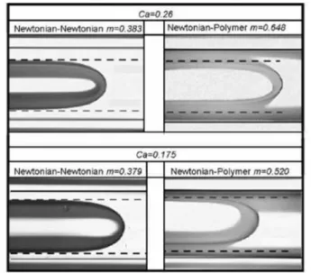
In Figure 10 is shown the fraction of mass deposited m as a function of Ca for the case when a Newtonian liquid (Soil Bean Oil) is used to displace the more concentrated viscoelastic solution, namely Polymer-B. Again, the results are confronted with the data obtained for the displacement of a Newtonian liquid by another at same viscosity ratio. Over the entire range of capillary number investigated, it is observed a thicker liquid film attached to the wall whenPolymer-B is the displaced material, as can be seen on images exposed in Fig. 11. These results are in qualitatively agreement with experiments performed by Huzyak and Koelling (1997). They observed an increase on m when gas was used to displace a viscoelastic solution.
Figure 10. Fractional mass as a function of capillary number at fixed viscosity ratioNη=1.8. The white dots correspond to the case of two Newtonian liquids
and the black dots are data obtained when the Polymer-B is displaced by the Newtonian liquid
Figure 11. Images of the tip of the interface for two capillary numbers,Ca=0.175:0.255, at fixed viscosity ratio, Nη=1.8. On the right, the
Polymer-B is displaced by a Newtonian liquid and on the left is the case when a Newtonian liquid is displaced by another.
Final Remarks
Experimental visualizations on liquid-liquid displacement in a capillary tube were carried out in order to investigate the fraction of mass deposited on the wall and the shape of the tip of the interface.
Recent articles which analyze liquid displacement in tubes are found in literature. However, these are limited to gas-liquid displacement or to liquid-liquid displacement of two Newtonian liquids. Thus, the main contribution of the present work was the study of liquid-liquid displacement in tubes when viscoelastic solutions are used as both displacing and displaced liquids.
and the Brazilian Agency of Petroleum (ANP).
References
Bretherton, F.P., 1960, “The montion of long bubble in tubes”, J. Fluid Mech., Vol. 10, pp. 166--188.
Dreher, K.D. and Gogarty, W. B., 1979, “An overview of mobility control in micellar - polymer enhanced oil recovery”, J. Rheology, Vol. 23 No. 2, pp. 209--229.
Vol. 127, pp. 24--31.
Soares E.J., Carvalho, M.S., Souza Mendes, P.R., 2006, “Gas-displacement of non-Newtonian liquids in capillary tubes”, Int. J. Heat and Fluid Flow., Vol. 27, pp. 95--104.
Stark, J. and Manga, M., 2000, “The motion of long bubble in a network of tubes”, Transp. Porous Media, Vol. 40, pp. 201--218.