ABSTRACT: Resonant LCL-T converter can operate as stable voltage source, being fed from current, for instance, the photovoltaic battery. It is shown that LCL-T resonant tank has intrinsic ability to convert stable AC current into stable AC voltage thus parametrically regulating output voltage at a ixed value. This mode of operation is made possible by the use of active (synchronous) rectiier to recoup energy from the output back to the LCL-T resonant tank. Basic characteristics of resonant LCL-T converter regulated by phase shift between inverter and rectiier regardless of a solar battery current drift have been deined. It is shown that phase control guarantees 0 voltage and 0 current on switching; however, turn-off current could be substantial. Calculations and assumptions made in this study have been conirmed by simulation and hardware prototype.
KEYWORDS: Spacecraft power supply system, Resonant converter, Bidirectional dual active bridge, LCL resonant converter, ZVS, ZCS.
LCL-T Resonant Converter Based on
Dual Active Bridge Topology in Solar
Energy Applications
Alexander Vladimirovich Osipov1, Yury Alexandrovich Shinyakov1, Vadim Nikolaevich Shkolniy2,
Michael Sergeevich Sakharov1
INTRODUCTION
Advancements in spacecrat (SC) power supply unit (PSU) are mostly related to enhancements in speciic energy parameters, notably size, weight, and eicacy. Contemporary power converters in PSU are presented by non-isolated boost types controlled by pulse width modulation (PWM). he most prohibitive feature of such converters is hard commutation of switching devices, being a source of high losses as well as electromagnetic interference (EMI). he mitigation of hard switching shortcomings by introduction of various snubbing circuits to provide resonant switching transitions is not helpful due to added complexity and need for additional active elements to be commutated in the very same way (Pavlovic et al. 2012; Shiva Kumar et al. 2015; Bodur et al. 2003; Akın 2014; Goryashin and Khoroshko 2011). he commutation itself becomes too long and quite oten creates unwanted oscillations thus increasing safety margin required and limiting conversion frequency as well as regulation range. All of this have led to the use of dual active bridge (DAB) resonant converters (Hillers et al. 2012; Selvaperumal et al. 2009; Sowjanya and Raghavendran 2013; Krismer and Kolar 2009; Osipov et al. 2015; Shivaraja 2015), including series LC tank, which is a resonant circuit. Sinusoidal waveform of inverter current automatically provides sot switching without axillary components. However, the energy source of SC PSU is usually a photovoltaic (PV) battery. It operates as current source while voltage is usually limited by isolation breakdown level in vacuum. At the same time load can vary a lot. Typical resonant LC converter cannot be used as a voltage regulator
1.Tomsk State University of Control Systems and Radioelectronics – Institute of Space Technologies – Research and Development Institute of Space Technologies – Tomsk/Tomsk – Russia. 2.Reshetnev Company – Information Satellite Systems – Department 600 – Zheleznogorsk/Krasnoyarsk – Russia.
Author for correspondence: Alexander Vladimirovich Osipov|Tomsk State University of Control Systems and Radioelectronics – Institute of Space Technologies | 40 Lenina Prospect | 634050 – Tomsk/Tomsk – Russia | Email: [email protected]
just because no-load condition will force the PV battery to operate in voltage source mode, creating high voltage across its terminals and increasing the possibility of breakdown.
he solution for this problem is the use of LCL-T converters (usually referred as “inductive-capacitive converter” in the Russian literature), typically applied as alternating current (AC) source and fed by stable AC voltage. he performance of such converters was analyzed in Russia (Milach et al. 1964; Dozorov
2013) and elsewhere (Borage et al. 2005; Borage and Tiwari 2012;
Zouggar et al. 2000). However LCL converters can operate just
in opposite way converting current source into voltage source, which is exactly the task the converter should perform in PV battery fed by PSU. In that case input current deines resonant tank 1, which, in turn, makes the value of AC voltage at resonant capacitor near constant regardless the load. Interestingly enough no investigations of such mode of operation could be referredto. To date published research papers describe the operation of LCL-T converter with diode-based (passive or uncontrollable) rectiier in output current stabilization mode, for instance, Borage
et al. (2005). herefore, the purpose of this study was to analyze
resonant LCL-T converter in DAB coniguration as voltage source mode being fed by PV battery operating in current source mode.
METHODOLOGY
LCL-T RESONANT CONVERTER OPERATION IN CURRENT-TO-VOLTAGE CONVERSION MODE
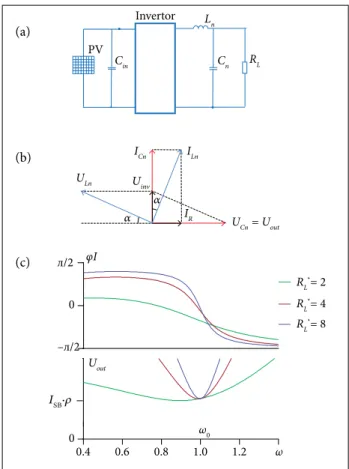
Transistors in resonant converters are commutated at the frequency near LC tank resonant 1, which provides sinusoidal current with near 0-value at switching instances, minimizing losses. Resonant tank can be loaded in diferent ways depending on the input source impedance. If the PV battery operates in voltage mode then the load is connected in series with the resonant tank (typical resonant DCDC converter) (Fig. 1а). If PV battery operates as current source the load is connected in parallel to the capacitor in resonant tank creating the so-called Boucherot circuit, in which circuit inverter’s output voltage is square by waveform. If the frequency equals to resonance 1 the current has sinusoidal waveform allowing switching transistors with minimal losses.
Regarding Boucherot circuit being fed by current source, capacitor’s current IСnamplitude is stable and actually does not
depend on the load; correspondingly output voltage is stable, picked up at terminals of the capacitor Сn, and the value is deined by the equation
where: ρ = √Ln/Cn is the tank’s characteristic impedance; Lnis the
inductance value of resonant inductor Ln; Cn is the capacitance
value of resonant capacitor Cn.
Accordingly, varying parameters of the resonant tank 1 may match the current level of PV battery to the output voltage required without the use of transformer allowing to have output voltage lower than the input one, i.e.RL< ρ, where RLmeans
load resistance.
In Busherot circuit (Fig. 1а) load current is the diference between capacitor and inverter ones, while capacitor’s current is stable by amplitude and is in phase with inverter’s voltage; inverter current is lagging voltage U1м by angle α, depending
on the load (Fig. 1b):
Figure 1. Series LC resonant converter. (a) Circuit; (b) Vector diagram; (c) Bode plot for phase and gain.
PV
RL
Cn
ICn
UCn = Uout
Uout
ULn Uinv
α α
ILn
IR Ln
Cin
Invertor
0.4 0.6 0.8 1.0 1.2 ω
ω0
φI
0
л/2
–л/2
0 ISB·ρ
RL*= 2
RL*= 4
RL
*= 8
(1)
Voltage across the load UCnis shited in respect to inverters
one by π/2.
(2)
(a)
(b)
Frequency-related behavior of the resonant converter, plotted for diferent normalized load values RL * = RL/ρ, is shown in
Fig. 1c. It is clear that the shunting inluence of the load shits resonant frequency of the tank in accordance with
by the vectors Uinv, ULn, UCn, and UR, ULf, UCn, which leads to ULn= Uout ; the stability of output voltage because the change
in Uinv is compensated by ULf.
In that case the phase of capacitor current is shited in regard to the inverter’s one by the angle αdeined by the load
PV
RL
Cn
ICn
UCn
ULf
ILf
ILn
Uout
Uout
ULn αUinv
α Ln Lf
Cin Invertor
0.6 0.8 1.0 1.2 ω*
φI
0
л/2
–л/2
0 ISB·ρ
RL*= 2
RL*= 4
RL
*= 8
(3)
(4)
(5)
(6)
(7)
If the frequency is ixed as ω0 = √1/LnCn the load increase
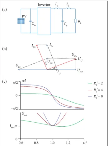
yields the phase shit deined in Eq. 2; in that case output voltage of an angular frequency ω0 becomes stable due to compensation by the inductor current. Bode plot shows that load increase leads to the loss of converter resonance properties. To reduce phase shit due to the load change LCL-T topology may be used (Fig. 2).
Figure 2. Resonant LCL-T converter. (a) Schematics; (b) Vector diagram; (c) Phase and amplitude responses.
he vector diagram of LCL-T converter (Fig. 2b) shows that in case of Ln= Lf an additional voltage drop across Lf
allows forming an angle equal to π/2 between the vectors of load current and inverter one regardless of the load. his condition can be met by the equality of right triangles formed
where: UPV represents photovoltaic voltage.
Frequency-related parameters of LCL-Т converter are shown in Fig. 2c. It can be observed that LCL-T tank allows stabilizing output voltage parametrically operating at the resonant frequency for the full load range.
LCL-T CONVERTER OPERATION ANALYSIS IN CURRENT-TO-VOLTAGE CONVERSION MODE WITH OUTPUT RECTIFIER
In order to supply constant output voltage one may need to use rectiier, bridge type, for instance (Fig. 3а), which substantially changes the converter behavior. Before anything else, the irst harmonic experiences least resistance
as a result, the output voltage can be deined as
So the resonant tank values could be deined as
he simulation for ixed output voltage Uout= 100 V, input
current IPV= 8 A, f = 50 kHz, and resonant tank parameters
taken in accordance with Eq. 7 shows that output current is discontinuous, distorting rectiier input voltage Urect, having ILf = 0 and Urect= UCn(Fig. 3b). The converter operates in
non-resonant mode, and output voltage value does not comply with calculated value Uout= 100 V, increasing along with the
load resistance. Idle operation is not possible. hese problems can be partially solved by operating frequency adjustment (Borage et al. 2005; Zouggar et al. 2000).
If one uses fully-controlled switches for rectiier, operation in continuous conduction mode could be forced and the aforementioned problems fixed by recouping energy from
and (a)
(b)
the output capacitor back to the resonant tank (Fig. 4а) thus making topology commonly referred as DAB. For proper operation output bridge control should be shited by π/2 in respect to inverter. his is exactly the phase between inverter and load currents (Fig. 2b).
From the simulation it is clearly veriied that, in order to stabilize output voltage at calculated value of Uout= 100 V,
regardless of the load, one needs to operate at resonant point in continuous conduction mode for active rectiier Irect
(Fig. 4b). Rectiier current Irect is not sinusoidal, being result
of the application of 2 voltages to output inductor, rectangular
Urect, and sinusoidal UCn, which is speciic to that topology.
As a result rectiier current contains sinusoidal as well as saw tooth components:
19.97ms 19.98ms 19.99ms 20.00ms
0V
-180V 180V-20 0 20
RL Lf
Ln
Cout Cn
Cn Uinv
Uinv
UCn
ULf Iinv
Irect Urect Urect
D3 D1
D4 D2 T3
T1
T4 T2 PV
-20 0 20
0V
-180V 180V -20 0 20
RL Lf
Ln
Cout Cn
Cin Uinv Urect
Urect
Uinv
UCn
ULf UL
Irect Iinv
T7 T5 T3
T1
T2 T4 T6 T8
PV
-20 0 20
19.96ms 19.97ms 19.98ms 19.99ms 20.00ms
0 π/2 π 3π/2 2π
-20 -10 0 10 20
ILf_sin
ILf_saw
ILf
-10 0 10 20
–20
α
0 π/2 π 3π/2 2π
Figure 3. (a) Resonant LCL-T converter with non-active
rectiier; (b) Operational waveforms at Uout = 100 V, I
PV = 8 A,
and f = 50 kHz.
Figure 4. (a) Resonant LCL converter in DAB coniguration
schematics; (b) Operational waveforms at Uout = 100 V, I
PV = 8 A,
and f = 50 kHz.
(8)
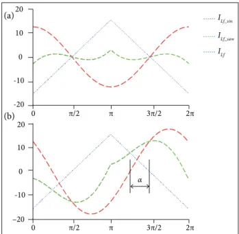
Rectiier current diagrams for a diferent load values are
shown in Fig. 5. For instance, at no load or idle capacitor’s, voltage is in phase with rectiier’s voltage, α = 0; saw tooth
Figure 5. Rectiier input current at the idle. (a) At normalized load
(no-load operation); (b) Nominal load operation: RL = π2/8ρ.
(a)
(a)
(b)
(b)
(a)
19.96 ms 19.97 ms 19.98 ms 19.99 ms 20.00 ms -20
0 20
-180 0 180
-20 0 20
ULn
UCn
ULf
ILf ICn
β
β β
α α
Iinv
Iinv
Uinv
Uout UL,f
Irect
Urect
Uc
Uinv π/2∙I
PV
π/2∙IPVρ
π/4∙U PV
Urect = 4/π∙Uout as well as sinusoidal components in current do have
equal fundamental harmonic and, correspondingly, there is no fundamental harmonic in the output current. Besides, averaged rectiied current is equal to 0 (Fig. 5а).
As we increase the load phase shit between capacitor and rectiier voltages, α starts to appear, and capacitor’s voltage starts (Fig. 5b). In the case when RH= π2/8ρ, i.e., at the valueRH*= 1,
phase shit α= π/4 and rectiier’s current contains fundamental harmonic
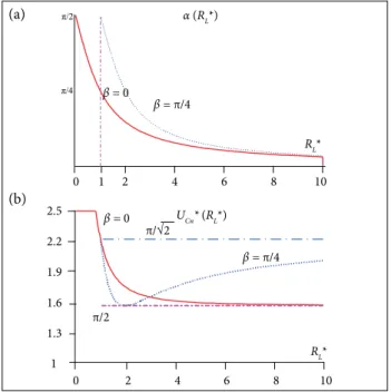
Regulation curves are shown in Fig. 7. It is clear that the angle of control α depends on the control angle β, while
minimum capacitor voltage occurs if α = β, and it corresponds to
UCn
*
= (π/2)(1/cosβ); in case of β = π/4 and RL * → ∞ , the voltageacross Cn would beUCn* = (π/√2).
For a given case there are diagrams shown in Fig. 6b. If PV battery current is decreased to IPV= 5.6 А, σIPV= √2 and
RL *= 2, in accordance with Eq. 10; to produce previous output voltage level, control angle β = π/4 is necessary, meaning α = β. hus using Eq. 12 we can derive UCn = (2√2/π)Uout,
which is shown in the diagram of Fig. 6b.
Commutation mode of switches in LCL-T converter using phase regulation: the condition necessary for ZVS is the lag of rectiier voltage in respect to inverter’s voltage by π/2 + β.
(9)
(10)
his way output current depends on load phase angle α.
PHASE SHIFT CONTROL OF LCL-T RESONANT CONVERTER
One of the most important PV battery features is instability of the output current level, which depends on quite a few external conditions like illumination change during shade-light transition, eiciency degradation due to radiation, etc. Such efects can be compensated by the shiting control of rectiier
Urect in respect to inverter voltage Uinv by phase β. For classic
DAB implementation, such method of control is described in Pavlovic et al. (2012). As a result of current recoup into a
resonant tank, output voltage would rise. he process of control is shown in details in the vector diagram of Fig. 6а.
If we shit rectiier control by the angle β it shits rectiier
current phase to the very same value in respect to rectiier input voltage, forcing output voltage Uout to rise in accordance with
Figure 6. Phase regulation in resonant LCL-T converter with active rectiier. (a) LCL-T converter vector diagram of phase
regulation process; (b) Operation diagram at I
PV = 5.6 A, β = π/4,
RL = 25 ω, and RL* = 2.
It is very important to hold phase shit of π/2 between inverter voltage Uinv and rectiier current Irect to provide conditions for
parametric stabilization of the output voltage, because it will preserve the equality of triangles formed by the vectors Uinv, ULn, UCn and Urect, ULf, UCn, respectively.
Angle α is determined by the load value similarly to the
previous case and could be calculated as follows:
where: RL * = (8/π2)(RL/ρ) is the normalized load value.
Angle α, in turn, deines voltage across Сn:
(11)
(12) and
(a)
0 1 2 4 6 8 10
0 2 4 6 8 10
1 1.3 1.6 1.9 2.2 2.5
α (RL*)
UCn* (RL*)
RL*
RL*
β = π/4
β = 0
β = 0
π/√2
π/2
β = π/4
Iinv (5 A/div) Iinv (5 A/div)
Iinv (5 A/div)
Irect (5 A/div) Irect (5 A/div)
Irect (5 A/div) Uinv (50 A/div)
Uinv (50 A/div) Uinv (50 A/div)
л/2 л/2 л/2
Urect (50 A/div)
Urect (50 A/div) Urect (50 A/div)
Time (2.5 us/div)
Time (2.5 us/div)
Time (2.5 us/div)
Time (2.5 us/div)
Time (2.5 us/div)
Time (2.5 us/div)
19.96 ms 19.97 ms 19.98 ms 19.99 ms
0 20
-10 0 20
-10
IVT inv UVT inv
UVT rect
IVT rect π/2 + β
Such control mode provides conditions for turning transistors ON. Commutation transitions depend on a bridge place. In the inverter, one has to make commutation before the current changes the sign (Fig. 8b), which provides turning in the complementary switch at reverse bias or 0 voltage across. In rectifier, one has to make commutation after the change of the current sign (Fig. 8). This way, in order to provide ZVS, one has to supply a leading current phase of the inverter and a lagging one for the rectifier.
Figure 8. Current and voltage waveforms of rectiier and inverter in resonant LCL-T converter using phase control.
Figure 7. (a) Control angle α; (b) Resonant capacitor
voltage, UCn, versus normalized load in the LCL converter.
Figure 9. Operating diagrams for different load values of the LCL-T converter. (a) RL = 18 ω; (b) R
L = 6 ω; (c) Idle (RL = ∞).
Turn off transition occurs at rather high current; however, proper snubbing capacitor across the switch or even transistor’s output capacitance together with dead time adjustment does provide proper commutation.
(a)
(b)
RESULTS
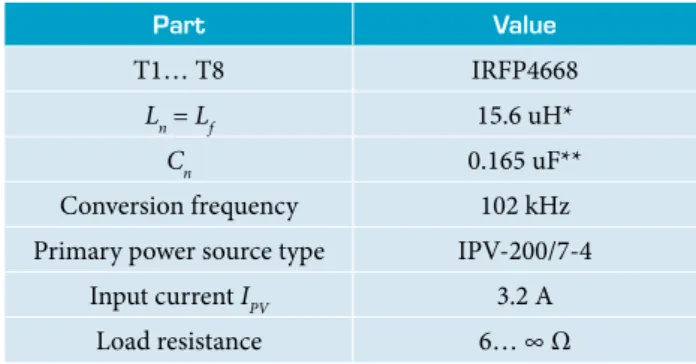
he components used in hardware prototype are shown in Table 1. To verify simulation data hardware prototype has been built (Fig. 4a) Actual operation diagrams are presented in Fig. 9. he parametric stabilization obtained 2%, and sot commutation could be observed in all cases.
*ETD34/17/11 N = 28 turns; **К78-2-315В-0.033 uF 5 pcs.
Table 1. Components used in the hardware prototype.
then output voltage stays at 60 V. Variation of the load resistance does change input current consumed.
Part Value
T1… T8 IRFP4668
Ln = Lf 15.6 uH*
Cn 0.165 uF**
Conversion frequency 102 kHz
Primary power source type IPV-200/7-4
Input current IPV 3.2 А
Load resistance 6… ∞ ω
up to the full load. Moreover, for operation at the idle unlike the state-of-the-art prototypes (Pavlovic et al. 2012; Hillers et al.
2012; Selvaperumal et al. 2009), there is no need for frequency
adjustment, which in turn eases control efort.
ACKNOWLEDGMENTS
The study was performed during the execution of a complex project (number 02.G25.31.0182) with the financial support of the Russian Government (Ministry of Education of Russia).
AUTHOR’S CONTRIBUTION
Osipov AV, Shinyakov YA, and Shkolniy VN conceived the idea and co-wrote the main text; Osipov AV and Sakharov MS performed the experiments; Sakharov MS prepared the igures. All authors discussed the results and commented on the manuscript.
CONCLUSION
Resonant LCL-T converter has the ability to convert the current source into the voltage one, which best serves for SC PSU where the primary source is PV battery. hrough the use of an active rectiier, LCL-Т converter provides high accuracy of parametric stabilization of the output voltage from the idle
REFERENCES
Akın B (2014) An improved ZVT–ZCT PWM DC–DC boost converter with increased eficiency. IEEE Trans Power Electron 29(4):1919-1926. doi: 10.1109/TPEL.2013.2269172
Bodur H, Bakan AF, Baysal M (2003) A detailed analytical analysis of a passive resonant snubber cell perfectly constructed for a pulse width modulated d.c.–d.c. buck converter. Electr Eng 85(1):45-52. doi: 10.1007/s00202-002-0141-7
Borage M, Tiwari S (2012) AC analysis of resonant converters using PSpice. A quicker approach. Asian Power Electronics Journal 6(2):1-6.
Borage M, Tiwari S, Kotaiah S (2005) Analysis and design of an LCL-T resonant converter as a constant-current power supply. IEEE Trans Ind Electron 52(6):1547-1554. doi: 10.1109/TIE.2005.858729
Dozorov SA (2013) Research and development of inductive-capacitive power source (PhD thesis). Saint Petersburg: Saint Petersburg Electrotechnical University “LETI”. In Russian.
Goryashin NN, Khoroshko AY (2011) On increasing the energy eficiency of a pulsed voltage converter with a resonant switching. Bulletin SibSAU 4(37):20-24.
Hillers A, Christen D, Biela J (2012) Design of a highly eficient bidirectional isolated LLC resonant converter. Proceedings of the 15th International Power Electronics and Motion Control Conference.
Krismer F, Kolar JW (2009) Accurate small-signal model for the digital control of an automotive bidirectional dual active bridge. IEEE Trans Power Electron 24(12):2756-2768. doi: 10.1109/TPEL.2009.2027904
Milach AN, Kubyshkin BE, Volkov IV (1964) Inductive-capacitive voltage
converters in current sources. Kiev: Naukova Dumka.
Osipov AV, Shinyakov Yu A, Chernaya MM, Tkachenko AA (2015) Resonant converters Solar energy. Proceedings of the 19th International Scientiic Conference “Reshetnev’s Readings”. Krasnoyarsk; Russia.
Pavlovic Z, Oliver J, Alou P, Garcia O, Cobos J (2012) Bidirectional dual active bridge series resonant converter with pulse modulation [accessed 2016 Jun 3]. https://www.researchgate.net/publication/254019572_Bidirection-al_Dual_Active_Bridge_Series_Resonant_Converter_with_pulse_modulation
Selvaperumal S, Christober C, Rajan A (2009) Embedded control of LCL resonant converter analysis, design, simulation and experimental results. Engineering 1(1):7-15. doi: 10.4236/eng.2009.11002
Shiva Kumar S, Panda AK, Ramesh T (2015) A ZVT–ZCT PWM synchronous buck converter with a simple passive auxiliary circuit for reduction of losses and eficiency enhancement. Ain Shams Engineering Journal 6(2):491-500. doi: 10.1016/j.asej.2014.10.018
Shivaraja L (2015) Modeling and simulation of LLC resonant converter for photovoltaic systems. International Journal of Emerging Technology and Innovative Engineering 1(4):175-179.
Sowjanya K, Raghavendran P (2013) Isolated bidirectional full-bridge DC-DC converter with a lyback snubber. International Journal of Soft Computing and Engineering 3(2):16-25.