FINITE ELEMENT ANALYSIS OF STEEL BEAMS WITH WEB
APERTURES UNDER FIRE CONDITION
A. Kada1, B. Lamri1, L. Mesquita M.R.2 and A. Bouchair3 1
Laboratory of Structures, Geotechnic and Risks, Hassiba Benbouali University of Chlef, Faculty of Civil Engineering and Architecture, Route de Sendjas, Chlef 02000, Algeria
2
Polytechnic Institute of Bragança, Campus Sta Apolónia Apartado 1134, 5300-857 Bragança, Portugal
3
Clermont Université, Université Blaise Pascal, Institut Pascal, BP 10448, 63000 Clermont Ferrand, France
Received: 20 March 2016; Accepted: 27 May 2016
ABSTRACT
This work is intended to analyse the behaviour steel beams with apertures under high temperatures rise due to fire using finite elements simulations with ANSYS software. It includes a structural fire analysis and a comparative study of cellular and castellated steel beams which takes into account transient temperature effect, material and geometric non-linear behaviour. FE models which estimate limiting time, mid-span deflection and failure temperature are presented for hexagonal and circular types of web opening shapes under several uniform load levels. The study shows that for any beam with closely spaced openings failure in fire will in most cases be caused by failure of the steel web. The numbers of web-openings and cells as well as their shapes are critical for the behaviour of castellated sections and cellular beams under fire condition.
Keywords: ISO834 fire; web-aperture; cellular beam; finite element modelling; time-deflection behaviour; ANSYS.
1. INTRODUCTION
Steel cellular and castellated beams are being widely used in multi-storey buildings when long spans are required with a major benefit of using apertures to accommodate the under floor ducts [1], Fig. 1 [2]. The apertures however induce some penalties, at ambient on the load carrying capacity [3,4] and on the vertical displacement increase in the region of web openings [5] as well as on volume for calculation of section factor at elevated temperatures
vertical deflections, limiting temperatures and failure modes is done among the different types of open-web beams to show the influence of opening spacing.
2. BEAM GEOMETRY AND STRUCTURAL DESIGN AT ROOM TEMPERATURE
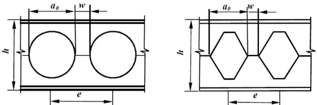
Castellated and circular openings are obtained by oxycutting or plasmacutting process on a I parent profile in the appropriate pattern, half hexagonal line or circular by a double pass cutting, after which the two halves are separated and welded together [2] Fig. 1.
The geometry of such beams is guided by two most important parameters, the diameter a0 and the web post width w. In the present study all steel beams are from hot rolled IPE500 parent I section of class 1 and web openings are located along the centreline of the web on a 7m span. The outlined dimensions in Fig. 2 are from EC3 annex N [16] and the geometrical parameters for web post width and ratio of opening spacing are set according to the following prescribed limitations and guidelines [11,34]:
The width w of the web post should be at least equal to 130 mm; The ratio e/a0 should at least equal to 1.25;
The ratio h/a0 should be at least equal to 1.25 and not greater than 4.0;
e is the spacing between regular openings and h is the total height of the beam
Diameter of cells and the width of hexagons is a0 =38 cm and kept constant for all cases.
The beams of steel grade S355 are simply supported, pin-roller, and subjected to a uniformly distributed load. A preliminary design at ambient using ACB+ software [34] was conducted to work out the ultimate load qult that checks, cross-section resistance at
web opening and post locations, shear buckling of the web and resistance of the beam to the lateral torsional buckling according to the principles of Eurocode 3 [15]. Table 1 is a summary of the dimensions and load design values qEd at room temperature for cases of
study.
Figure 2. Geometric shapes & Properties of beams with web opening
Table 1: Open web beams dimensions and loads
Dimensions CELL10/HEX10 CELL11 CELL12/HEX12 CELL13
w(mm) 285 220.02 170 152
e(mm) 665 600.02 550 532
α=e/a0 1.8 1.6 1.5 1.4
qEd(kN/m) 73.51 72.84 73.33 72.89
CELLn, HEXn stands for cellular and castellated beam with n regular openings.
For castellated beams, the height of the hexagonal opening is worked out to get the closest possible match with the circular surface shape for a corresponding cellular beam with the same number of openings. They are also subject to the same design load value qEd to allow for possible comparisons between numerical models in the subsequent analyses under fire conditions.
3. FIRE ACTION AND STRUCTURAL RESPONSE
3.1 Fire curves
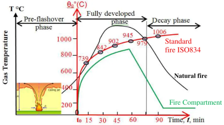
A real fire curve is characterized by 3 phases: a pre-flashover phase, a fully developed phase and a decay phase and can be simplified by a parametric compartment fire Fig. 3 [35]. Most structural damage occurs during the fully developed fire phase and only the fully developed fire phase is taken into account. The reference time t0, Fig. 3, is regarded as the origin of the temperature-time coordinate system, corresponding to the point of flashover. EC1 [33] proposes a standard fire curve called ISO 834 which represents a single phase ever rising gas temperature θ in o
C, Fig. 3, at time t in minutes according to the following equation:
8 1
log 345
20 10
t
g
Figure 3. Fire curves – 3 phases real fire vs ISO 834 & compartment fire model
3.2 Material property at elevated temperatures
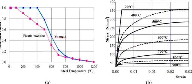
The response of structural steel members under fire conditions is governed by thermal Fig. 4, mechanical properties and deformation Fig. 5 [24]. The strength of steel decreases as the temperature increases beyond 400°C and the stiffness also decreases with increasing temperature as the Young’s modulus begins to decrease earlier at 100 ºC Fig. 5(a) [35]. The steel mechanical behaviour follows relationships given in EN1993-1-2 [24] and in all simulations material’s non -linearity is established by means of stress-strain diagram in Fig. 5(b).
The nominal value for the structural strength fy20, Young’s modulus E and Poisson’s ratio ν are 355 N/mm2
, 21.104 N/mm² and 0.3 respectively for parent solid and open-web steel beams cases of study.
(a) (b)
Figure 4. Steel thermal properties vs temperature (a) Conductivity & specific heat; (b) Thermal expansion
Standard fire ISO834
Fire Compartment
(a) (b)
Figure 5. Steel mechanical properties vs temperature (a) Variation in design strength and elastic modulus; (b) Stress-strain curve
3.3 Failure modes and failure criteria of open web steel beams
At ambient a beam containing web holes should be checked against number possible failure modes such as global bending and vertical shear, web-post bending and horizontal shear, web-post buckling and Vierendeel bending [9,10]. These make two groups of criteria for plastic resistance and for resistance to instability checked for the beams at room temperature using ACB+ design tool from which the ultimate limit state load is worked out Table 1. For the fire condition, the mode of failure may differ from that at the ambient condition as the temperature increases, the elastic modulus of the section decreases at a greater rate than the yield strength Fig. 5(a). Particularly for steel beams with web openings, previous studies have shown that the critical temperature attained in the steel beam is also influenced by opening geometry, size and opening spacing [19,26]. Throughout this work the main assessment of fire resistance of the steel beams consists on the determination of the limiting temperature and the corresponding heating up time when the beams are analysed by the ANSYS software. Comparison is done against critical temperatures obtained using the ACB+ software for different cases presented. The main representative results at failure time, failure behaviour, maximum vertical displacements and temperature profiles are presented.
4. EUROCODE APPROACH FOR TEMPERATURE INCREASE IN UNPROTECTED STEEL BEAMS
The design temperature of the unprotected steel beams is calculated based on the simple method provided by EN 1993-1-2 [24] which assume an equivalent uniform temperature distribution throughout the cross section.
The increase in steel temperature during a small time interval is calculated with a
default. Considering that the temperature of the section at time ti is equal to θa,t(i), the
temperature θa,t(i+1) in time ti+1 = ti+ Δt is determined as follows:
θa,t(i+1) = θa,t(i)+Δθa,t
∆𝜃𝑎,𝑡 =𝑘𝑠
1
𝑐𝑎 𝜌𝑎(
𝐴𝑚
𝑉 ) 𝑛𝑒𝑡,𝑑∆𝑡
(2)
where 𝑘𝑠 is the correction factor for shadow effect; 𝐴𝑚 𝑉 is the section factor associated with the steel section [1/m] by default ksh = 0.7 (value for the rebuilt section) [19]; 𝜌𝑎 is the density of the steel [kg/m3]; 𝑐𝑎 is the specific heat of steel [J/kg K] Fig. 4a [24]; 𝒉 𝒏𝒆𝒕,𝒅 the net heat flux [W/m²], representing the thermal actions to which the surface of the member is exposed.
The net heat flux is determined considering the heat transfer by convection and radiation.
𝒉 𝒏𝒆𝒕,𝒅 = 𝛼𝑐 𝜃𝑔− 𝜃𝑚 + Φ𝜀𝑚𝜀𝑓𝜎 𝜃𝑔+ 273
4
− 𝜃𝑚 + 273 4 (3)
where 𝛼𝑐 is the coefficient of convection taken here as 25 W/m²K for standard fire curve ISO 834; θg is the gas temperature calculated by equation (1) for the normalized ISO curve;
𝜃𝑚 is the surface temperature of the member; Φ is a configuration factor taken equal to 1;
𝜀𝑚 is the surface emissivity of the member taken as 0.7 for carbon steel; εf is the emissivity of the fire, taken as 1; σ is the Stephan Boltzmann constant equal to 5.67x10⁸ [W/m2K4].
The method of calculating section factor for steel beams with apertures is treated in a different manner than in the case of solid steel section and should be calculated at the level of the web post as well as at the net section at the level of an opening [19].
The critical heating up time is reached when θa,t = θa,cr .The critical temperature θa,cr at time t for a member is determined for any degree of utilization μ0 and evaluated using analytical approach from EN 1993-1-2 [2].
𝜃𝑎,𝑐𝑟 = 39.19𝑙𝑛
1
0.9674𝜇03.833 −1 + 482 °𝐶 (4)
The degree of utilization µ0 is basically the design loading in fire as a proportion of the design resistance at ambient temperature (or at time t=0) but using the material partial safety factors which apply in fire design rather than in normal strength design.
5. FINITE ELEMENT MODEL AND VALIDATION
5.1 Structural model at room temperature
The finite element software ANSYS [32] was used to investigate the behaviour of web aperture steel beams. Structural SHELL181 finite element model is generated throughout both flanges and web of the different beams with nonlinear material and large displacement behaviour considered in the analyses. This finite element presents four nodes with six DOF per node which are translations and rotations on the X, Y, and Z axis, respectively Fig. 6.
The Finite Element Model was first verified at room temperature against the numerical model of simply supported steel beams with a single opening, case D41, established by Flavio R. et al. [15]. It uses restrictions applied on appropriate nodes to simulate applied load and support present in the later model to allow for comparison.
The model material non-linearity was considered through a bilinear elastoplastic response with a 5% strain hardening and a 205,000 MPa Young’s modulus. During the numerical investigation it was ensured that the collapse model avoids lateral torsional buckling by applying lateral restrains along the top flange of the beam span. The load-displacement curve (Fig. 6) obtained from FEM simulation agree very well by which a load capacity of 648.433 kN is depicted and the validity of the FEM can be proved.
Figure 6. (a) Finite element Shell181 [32]; (b) Load-displacement curve
5.2 Thermal model
A heat transfer analysis is carried out using the thermal SHELL131 [32], Fig. 7(a), with four nodes 3-D layered shell element, Fig. 7(a), having in-plane and through thickness thermal conduction capability applicable to a 3-D transient thermal analysis. The simulations account for radiation with the emissivity coefficient r of 0.7 at steel surface and convection αc being 4 W/m2K and 25 W/m2K for room and fire temperatures respectively [24,35].
Figure 7. (a) Thermal SHELL131, (b) Temperature distribution at reference time of 20 minutes
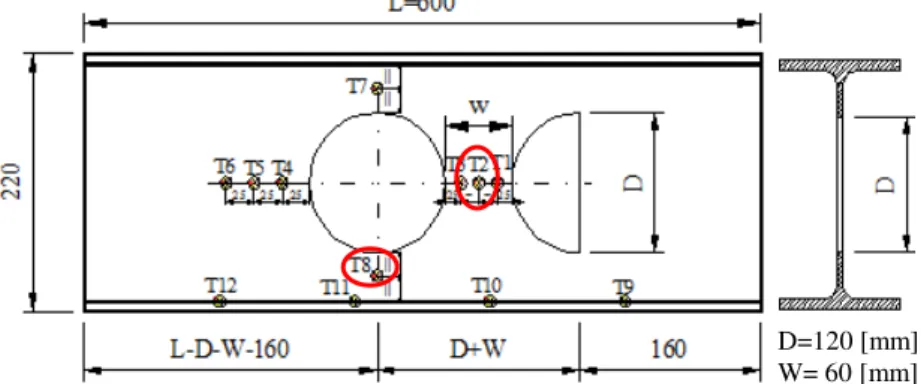
Validation of the thermal model is done against experimental fire furnace test P5 [21] performed among several ones at the Polytechnic Institute of Bragança to evaluate the behaviour cellular beams under fire condition. The section is made from hot rolled IPE220 steel profile with 600 [mm] length with circular holes cut directly into the web as represented in Fig. 8.
Figure 8. Dimensions of the P5 cellular beam and position and numbering of thermocouples
Figure 9. Cellular beam P5 in furnace test
A ceramic mat layer of 50 [mm] is applied on top and the beam ends also insulated by an equivalent ceramic mat to avoid the heat transfer from the ends, as can be seen in Fig. 9.
D=120 [mm] W= 60 [mm]
T2
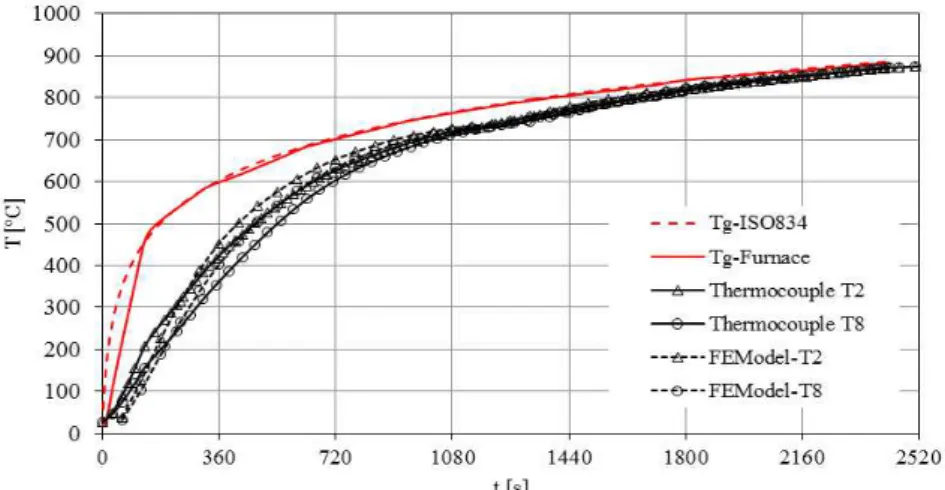
The steel temperature evolution of the test was measured by the attached thermocouples. Comparison of temperature evolution with the thermal finite element model would be on the web post temperatures at the thermocouples T2 and T8. The finite element model in ANSYS has given good prediction for temperature evolutions as by the thermocouples Fig. 10.
Figure 10. Tg-ISO curve, Tfurn-Temperature inside the furnace T2, T8 Thermocouples temperatures, ANSYS-FE steel temperatures
6. THERMAL–MECHANICAL MODEL SIMULATIONS
6.1 Temperature fields on steel beams
A thermal model as presented above is adopted with a refined finite element mesh taken around holes in the finite element model generated. FE Heat transfer into parent solid and open-web steel beams with circular and hexagonal openings of various sizes and locations along their beam length, Fig. 2, is simulated and analyzed using ANSYS software [29] to work-out the temperature field. The steel beams are exposed on three sides assuming that top flange will support a concrete slab and temperature in a steel member isn’t evenly distributed within the across section. Finite element heat transfer simulations yield non-uniform temperatures because of the actual boundary conditions and web thickness. A parent solid beam IPE500, four cellular beams with different number of openings and two castellated beams, see Table 1, are simulated according the thermal model presented above (§5.2).
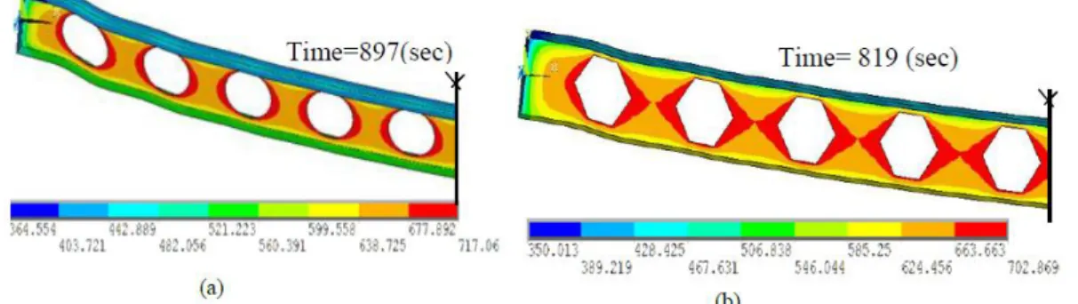
Temperature contours for CELL10 and CELL12 cellular beams and HEX10 and HEX12 castellated steel beams are shown respectively in Fig. 13(a), (b) and Fig. 14(a), (b). Limiting times and limiting temperatures for all the remaining cases are reported separately in Tables 3 and 4.
Figure 13. Contour temperatures in steel beams (η=0.6): (a) cellular CELL10; (b) Castellated HEX10
A
C
B
Figure 12. Parent IPE500 Solid-Beam Temperatures
E C3
Figure 11. Contour temperatures -Solid Beam IPE500
Figure 14. Contour temperatures in steel beams (η=0.6): (a) cellular CELL12; (b) Castellated
HEX12
6.2 Mechanical behaviour of beams with web apertures
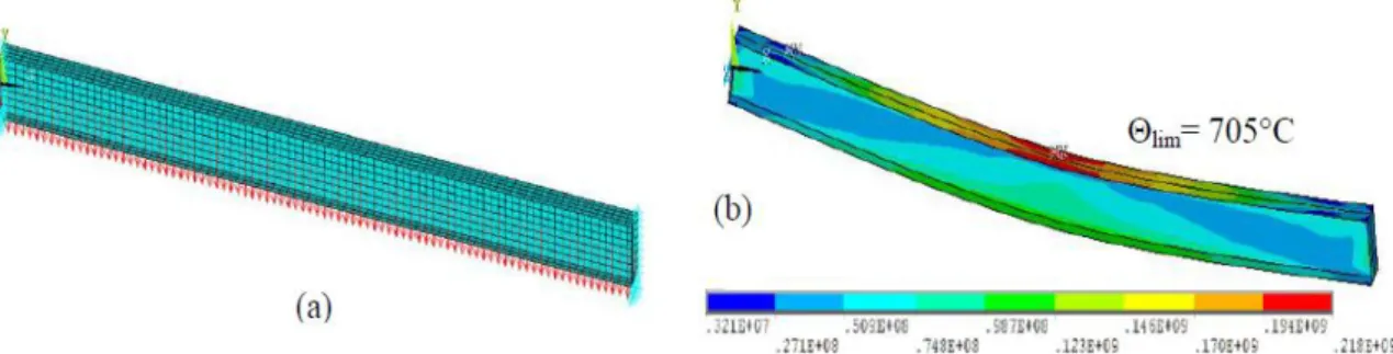
In the mechanical model, the thermal finite element SHELL131 is switched to structural finite element SHELL181. The steel beams are simply supported with pinned-rolled end conditions under uniformly distributed applied loads with no lateral torsional buckling. For the simply supported solid-beam (parent) the FE ultimate load of 123.3 kN/m is scaled by 0.6 representing the fire load level ηfi.
For beams with web apertures several fire load levels ηfi (1.0, 0.8, 0.5, 0.6, 0.4 and 0.2) are considered for different cases, Table 1. Simulations using the temperature fields generated at thermal analysis stage include thermal properties variation with temperature rise and account for nonlinear material and large displacement behavior.
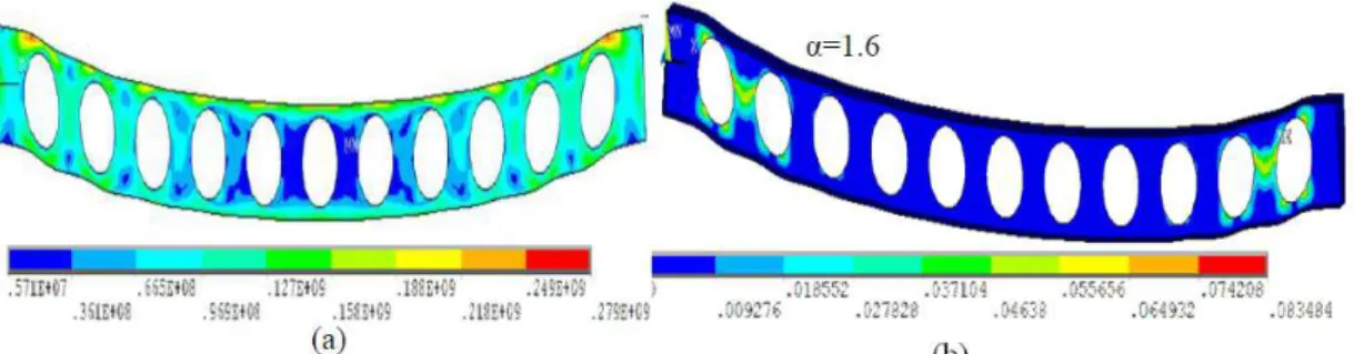
Finite element model boundary conditions and von Mises stress contour are presented in Fig. 15 to 19 for solid beam (parent), cellular beams CELL10 and CELL12 and for castellated steel beams HEX10 and HEX12 respectively.
Figure 16. Cellular beams CELL10, (η=0.6): (a) Structural FE Model CELL10, (b) Failure due to Vierendeel bending (von Mises plastic strains)
Figure 17. Cellular beam CELL11 (η=0.6): (a) Stress contour, (b) Failure due to Vierendeel bending (von Mises plastic strains)
Figure 18. Cellular beams CELL12, (η=0.6): (a) Structural FE Model , (b) (C) Web-Post failure (von Mises plastic strains)
Figure 20. Castellated beam HEX10: (a) Structural Finite Element Model ηfi=0.6; (b) von Mises strain, (c) von Mises stress, Vierendeel bending failure
Figure 21. Castellated beam HEX12: (a) Structural Finite Element Model ηfi=0.6; (b) von Mises stress, Vierendeel failure
7. RESULTS AND DISCUSSION
For the case of solid beam parent element thermal analysis results is presented and a comparison is made with analytical approach. The finite element thermal transient analysis shows steel temperature curves on both flanges and web which are plotted against Eurocode3 steel section uniform temperature Fig. 12. It shows that the finite element model produced a realistic thermal response in which EC3 curve fits perfectly well with the web time-temperature evolution curve. Thermal analyses on beams with web apertures have shown that the web posts formed between openings have experienced a further increase in temperature relative to the solid parent beam and values for a reference time of 600 seconds
(c)
Θlim= 689°C
are shown in Table 2. For mechanical analyses for solid beam, the shell finite element model is based upon transient thermal analysis producing non-uniform temperatures within the beam cross-section and resulted in a higher critical temperature of 705°C compared to 626°C of EC3 simple calculation. The corresponding limiting time is 16.6 minutes with a maximum vertical displacement of 27.4 cm.
For the case of cellular beams, the study considers different number of apertures referred to as CELL10, CELL11, CELL12, CELL13, resulting in different spacing ratio α which obeys to the prescribed geometry limitations. The Eurocode calculation procedure using ACB+ software considering plastic resistance criteria produced critical temperatures for these cases and are presented in Table 3 for a fire load level ηfi=0.6.
Table 2: Temperature in the web at a reference time of 600 sec
Temperature in the web (°C)
Solid beam 536
Cell10 600
Cell11 617.4
Cell12 599.6
Cell13 607
Table 3: ACB+ critical temperatures for cellular beams
Critical Temperature (°C) Fire load ηfi=0.6
Position Cell10 Cell11 Cell12 Cell13
Opening section 571 572 571 572
Web-post 680 660 630 606
The corresponding limiting temperatures from finite element models, Table 3 are higher compared to critical temperatures from ACB+ analyses. Results from thermo-mechanical analyses considering the cellular beams mentioned above and castellated beams HEX10, HEX12 for several fire load levels, in the form of plotting of mid-span vertical displacements variation with time are presented in Figs. 22, 23 and 24. For global bending the vertical displacement at mid-span is the displacement considered when defining failure. One can observe that the mid-span deflection increased gradually and linearly with time up to a certain temperature, beyond which it falls due to higher loss in strength at higher steel temperature.
Figure 22. Mid-span deflection with varying time and different load levels for cellular beams CELL10, CELL11
Figure 23. Mid-span deflection with varying time and different load levels for cellular beams CELL12, CELL13
Table 4: Structural finite element fire analyses results for cellular beams for fire load η=0.6
Beam type CELL10 CELL11 CELL12 CELL13
e/a0 1.8 1.6 1.5 1.40
tlim (min) 14.95 13.93 12.38 10.47
Θlim(°C))(web) 717 704 685 659
Mid-span deflection(cm) 16.44 16.83 13.03 11.66
Table 5: Castellated beams fire analysis results for fire load η=0.6
Beam type HEX10 HEX12
tlim (min) 13.65 12.52 Θlim (°C))( web) 702 689 Mid-span deflection(cm) 20.37 15.91
The plots show that the limiting times and hence the critical temperature of beams depends on the load level and on the number of openings perforated along the span. Figs. 16(b), 17(b) 18(b) and 19(b) show the von Mises plastic strain contours and von Mises stress contours at elevated temperatures for different opening spacing corresponding to different web posts widths. One can observe the formation of plastic hinges touching the four angles of the apertures which corresponds to a Vierendeel failure mode for cellular and castellated beams, CELL10, CELL11 and HEX10 with high α values Figs. 16, 17 and 20. For smaller α values however and as the web post width gets narrow for the case of CELL12, CELL13 and HEX12, web post failure is depicted Figs. 18, 19 and 21.
For the later this is confirmed from Table 4 and Table 5 which shows that for smaller α values CELL12, CELL13 and HEX12, the mid-span deflection is relatively lower suggesting that a local failure has occurred elsewhere in the web-post. This is due to a higher steel temperature effect exceeding 600°C Table 4 and Table 5 , where the steel has less than half of its design strength and its Young’s modulus is reduced to about 20% of the room temperature value, Fig. 5.
Figure 25. Cellular beams – mid-span deflection
for ηfi=0.6
Figure 26. Comparison of mid-span deflection for Cellular-Castellated beams
5. CONCLUSION
REFERENCES
1. Kaveh A, Shokohi F. Cost optimization of castellated beams using charged system search algorithm, Iranian Journal of Science and Technology, Transactions of Civil Engineering, No. C1, 38(2014) 235-49.
2. Arcelor Commercial Sections S.A, http://http://www.arcelor.com.
3. Amayreh L, Saka MP. Failure load prediction of castellated beams using artificial neural networks, Asian Journal of Civil Engineering (Building and Housing), Nos. 1-2, 6(2005) 35-54.
4. Redwood RG, Cho SH. Design of steel and composite beams with web openings, Journal of Constructional Steel Research, 25(1993) 23-41.
5. Donghua Z, Longqi L, Jürgen S, Wolfgang K, Peng W. Elastic deflections of simply supported I beams with a web opening, International Conference Advance in Computational Modeling and Simulation, Science Direct: Procedia Engineering, 31(2012)315-23.
6. Bailey C. Indicative fire tests to investigate the behaviour of cellular beams protected with intumescent coatings, Fire Safety Journal, No. 8, 39(2004) 689-709.
7. Liu TCH, Chung KF. Steel beams with large web openings of various shapes and sizes: finite element investigation, Journal of Constructional Steel Research, No. 1, 6(2003) 159-76.
8. Naili EH, Nadjai A, Han S, Ali F, Choi S. Experimental and numerical modelling of cellular beams with circular and elongated web openings at elevated temperatures, Journal of Structural Fire Engineering, No. 4, 2(2011) 289-300.
9. Kerdal D, Nethercot D. Failure modes for castellated beams, Journal of Constructional Steel Research, No. 4, 4(1984) 295-315.
10. Chung KF, Liu TCH, Ko ACH. Investigation on vierendeel mechanism in steel beams with circular web openings, Journal of Constructional Steel Research, 57(2001) 467-90. 11. Bitar D, Martin PO, Galea Y, Dermaco T. Poutres cellulaires acier et mixtes: Partie1 Proposition d’un modèle pour la résistance des montants, Revue Construction Métallique, No. 1, 43(2006) 15-39.
12. Martin PO, Galea Y, Bitar D, Dermaco T. Poutres cellulaires acier et mixtes: Partie 2 Proposition de nouveaux modèles analytiques de calcul de la flèche, Revue Construction Métallique, No. 2, 43(2006) 15-33.
13. Durif S, Bouchaïr A, Vassart O. Experimental tests and numerical modelling of cellular beams with sinusoidal openings, Journal of Constructional Steel Research, 82(2013) 72-87.
14. Soltani MR, Bouchaïr A, Mimoune M. Nonlinear FE analysis of the ultimate behaviour of steel castellated beams, Journal of Constructional Steel Research, No. 2012, 70(2011) 101-14.
15. Flavio R, Pedro CG, Luciano RO, Sebastião AL. Finite element modelling of steel beams with web openings, SCIRP Engineering, 6(2014) 886-913.
16. EC3, ENV 1993-1-1. Design of steel structures – Part 1-1: General rules and rules for buildings, Annex N.
18. Lawson RM, Hicks SJ, Design of composite beams with large web openings, SCI P355, 2011.
19. Vassart O, Hawes M, Zhao B, Franssen JM, Nadjai A. Fire resistance of long span cellular beam made of rolled profiles (FICEB), European Commission final report, 2012.
20. ASFP. Fire Protection for Structural Steel in Buildings, Yellow book, 5th Edit, 1(2014). 21. Luís Mesquita, João Gonçalves, Gustavo Gonçalves, Paulo Piloto, Kada Abdelhak.
Intumescent fire protection of cellular beams, X Congresso de Construção Metálica e Mista, Coimbra, Portugal, 26 & 27, November 2015.
22. Nadjai A, Vassart O, Ali F, Talamona D, Allam A, Hawes M. Performance of cellular composite floor beams at elevated temperatures, Fire Safety Journal, 42(2007) 489-97. 23. Wang P, et al. Web-post buckling of fully and partially protected cellular steel beams at
elevated temperatures in a fire, Thin-Walled Structures, 2015.
24. EC3, EN 1993-1-2: 2005. Design of steel structures. General rules. Structural fire design.
25. Vassart O, Bouchair A, Muzeau JP, Nadjai A. Analytical model for the web post buckling in cellular beams under fire, Proceedings of Structures in Fire, 2008, pp. 813-823.
26. Wang P, Wang X, Liu M. Practical method for calculating the buckling temperature of the web-post in a cellular steel beam in fire, Thin-Walled Structures, 85(2014) 441-55. 27. Nadjai A, Petrou K, Han S, Faris A. Performance of unprotected and protected cellular
beams in fire conditions, Construction and Building Materials, 105(2016) 579-88. 28. Wong VYB, Burgess IW. The influence of tensile membrane action on fire-exposed
composite concrete floor-steel beams with web-openings, The 9th Asia-Oceania Symposium on Fire Science and Technology, Science Direct: Procedia Engineering, 62(2013) 710-6.
29. Bihina G, Zhao B, Bouchaïr A. Behaviour of composite steel-concrete cellular beams in fire, Engineering Structures, 56(2013) 2217-28.
30. Ellobody E, Young B. Nonlinear analysis of composite castellated beams with profiled steel sheeting exposed to different fire conditions, Journal of Constructional Steel Research, 113(2015) 247-60.
31. Nadjai A, et al. Full-scall test on a composite floor slab incorporating long span cellular beams, The Structural Engineer, No. 21, 89(2011) 18-25.
32. ANSYS ver 14.5. 7
33. EC1, EN 1991-1-2:2002: Actions on structure – Part 1 2: General actions. Actions on structures exposed to fire ACB+, v 3.08, ArcelorMittal.
![Figure 1. Flame Cutting process of castellated and cellular steel beams and openings integrating services [2]](https://thumb-eu.123doks.com/thumbv2/123dok_br/16980794.762894/3.892.138.741.247.472/figure-cutting-process-castellated-cellular-openings-integrating-services.webp)
![Figure 6. (a) Finite element Shell181 [32]; (b) Load-displacement curve](https://thumb-eu.123doks.com/thumbv2/123dok_br/16980794.762894/8.892.150.750.567.789/figure-finite-element-shell-b-load-displacement-curve.webp)