Spherical Tokamak Development in Brazil
G.O. Ludwig, E. Del Bosco, J.G. Ferreira, L.A. Berni, R.M. Oliveira,
M.C.R. Andrade, C.S. Shibata, M. Ueda, L.F.W. Barbosa
∗,
and the high-power microwave sources group,
J.J. Barroso, P.J. Castro, and H. Patire Jr
†Laborat´orio Associado de Plasma, LAP Instituto Nacional de Pesquisas Espaciais, INPE
12227-010, S˜ao Jos´e dos Campos, SP, Brazil
Received on 18 March, 2003. Revised version received on 19 August, 2003.
This paper describes the general characteristics of spherical tokamaks, or spherical tori, with a brief overview of work in this area already performed or in progress at several institutions worldwide. The paper presents also the steps in the development of the ETE (Experimento Tokamak Esf´erico) project, its research program, technical characteristics and operating conditions as of December, 2002 at the Associated Plasma Laboratory (LAP) of the National Space Research Institute (INPE) in Brazil.
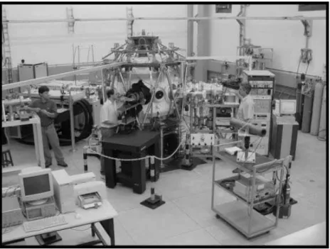
Figure 1. An overall view of the ETE spherical tokamak experiment.
1
Introduction
The ETE spherical tokamak (Experimento Tokamak Esf´erico) started its operational phase in late 2000 at the
As-sociated Plasma Laboratory of the National Space Research Institute in Brazil (ref Figure 1). It is devoted to the study of the operating regimes, confinement properties and current drive schemes in a low aspect ratio tokamak plasma
configu-∗Present Address: Faculdade de Engenharia, Arquitetura e Urbanismo, FEAU, Universidade do Vale do Para´ıba, UNIVAP, 12244-000, S˜ao Jos´e dos Campos, SP, Brazil
ration. This hot plasma magnetic confinement configuration [1] has been a subject of experimental study for a little over than one decade, offering the prospect of compact volumet-ric neutron sources and low-cost fusion power plants. Be-sides exploring the properties of low aspect ratio tokamaks, the ETE experiment will allow diagnostics development and training in tokamak operation, with a research program open to collaboration with other institutions. The initial operation of ETE is limited to the study of inductively heated plasmas. In the future, with the implementation of auxiliary heating methods, it will be possible to explore improved confine-ment regimes and means of current drive for steady-state op-eration. The large number of physics problems and technical issues that remain to be explored and solved in the spheri-cal torus configuration allow to perform, even in a modest device, a research program that can contribute effectively to fusion research.
2
Spherical
tokamak
experiments
worldwide
The spherical tokamak concept was tested in the late eighties by the insertion of current-carrying central rods into small existing devices [2][3][4]. These experiments were limited to cold plasmas (electron temperatures of a few tenths of eV) but gave evidence to the advantage of combining the favor-able characteristics of both the compact torus and the con-ventional tokamak. Figure 2 shows the location of the spher-ical torus (ST) in the three dimensional (A,q,β) space, rel-ative to the spheromak, field-reversed configuration (FRC), conventional tokamak, and reversed-field pinch (RFP) de-vices. The aspect ratioA=R0/ais the ratio of the major
to the minor radius of the plasma torus, the safety factorq is related to the rate of change of toroidal flux with poloidal flux, and theβvalue gives the ratio of the plasma kinetic pressure to the magnetic pressure. The elongation factorκ, which gives the ratio of the length of the poloidal cross sec-tion along the symmetry axis to the length along the equa-torial plane, can be seen on this diagram from the plasma outline drawings.
The START (Small Tight Aspect Ratio Tokamak) ex-periment operated from 1991 to 1998 and was the world’s first tokamak to study hot plasmas (>100 eV) at aspect ratios A <2 [5][6]. A full account of START results is presented in reference [7]. It was the first representative of a series of worldwide spherical tokamak experiments put into oper-ation in the nineties, with main parameters listed in Table 1. In some cases, the parameters given in this table correspond to nominal values that may not have been reached yet. In the remaining of this section, a succinct description of the meth-ods of plasma formation used in these devices is presented, showing the similarities between the research programs car-ried out by the ST and compact torus communities.
✁ ✂ ✄ ☎ ✆ ✁ ✂ ✄ ✝ ✆ ✆ ✞✠ ☛ ☞ ✌ ✌ ✎✑ ✓✕ ✓ ✑ ✘ ✙ ✚ ✙✘ ✜ ☞✣ ✥ ✦ ★ ✎✕ ✓✑ ✁ ✂ ✄ ☎
Figure 2 Axisymmetric configurations. Spherical tokamaks present both the strong toroidicity effects of compact tori (notably mag-netic shear) and the good stability properties provided by the exter-nal toroidal field of conventioexter-nal tokamaks.
Table 1. Spherical tokamaks worldwide: (1) GB (shutdown), (2) GB, (3) US, (4) RU, (5) JP, (6) BR, (7) CN (commissioning), (8) IT (proposed).
R0 a κ B0 Ip Paux
Device m m T MA MW
LATE5 0.2 0.14 1.2 0.18 0.05 0.35 TS-35
0.2 0.14 2 0.2 0.08 -Proto-Sphera8
0.2 0.16 2.2 0.06 0.18 -HIT-II3
0.3 0.2 1.8 0.5 0.25 -ETE6
0.3 0.2 1.8 0.6 0.4 -SUNIST7
0.3 0.23 1.8 0.15 0.05 -HIST5
0.3 0.24 2 0.2 0.1 -START1
0.32 0.25 3 0.31 0.31 1 CDX-U3
0.34 0.22 1.6 0.23 0.07 -TST-25
0.36 0.23 1.8 0.4 0.2 -Globus-M4
0.36 0.24 2.2 0.62 0.5 3.7 Pegasus3 0.45 0.39 3 0.1 0.2 1
TS-45
0.5 0.42 3 0.5 0.3 -MAST2 0.85 0.65 3 0.52 2 6.4 NSTX3
0.85 0.68 2.5 0.6 1.5 13
Excepting LATE, the devices listed in Table 1 use in-ductive methods for plasma formation or sustainment, either transferring flux from an internal solenoid or trapping an ini-tial bias flux through the rapid reversal or increase of the current in external poloidal coils. The external coils method is less efficient than the standard ohmic heating technique due to limitations in the retention of the initial bias flux. Thus far, the sustainment of the spherical torus configura-tion, which depends in large part of the internal plasma rents, awaits the development of efficient non-inductive cur-rent drive techniques. This is an absolute requirement for steady-state operation of future reactors.
plasma facing component [9]. In the search for current drive amplification methods, the TS-3 (Tokyo University Spher-ical Torus-3) device was used, during its initial operating phase, to conduct tokamak-merging experiments and inves-tigate the relaxation and reconnecting mechanisms. In TS-3 the toroidal plasma is typically formed starting from the arc current between the external electrodes of two plasma guns, i.e., using DC helicity injection start-up, plus magnetic com-pression. Presently, the high power heating of the magnetic reconnection is being used in TS-3 and the larger TS-4 de-vice to study the high-βstability of spherical tori. In these experiments two spheromaks with opposite toroidal fields are merged to form an oblate FRC that is subsequently trans-formed into an spherical tokamak configuration by applying the external toroidal field [10].
The principal objective of the Proto-SPHERA experi-ment is to test an ultra low aspect ratio tokamak, with the central conductor replaced by an arc discharge, as a proto-type for a larger SPHERA (Spherical Plasma for HElicity Relaxation Assessment) device [11]. In this concept an ini-tial screw-pinch is driven unstable by increasing the arc cur-rent and then relaxes to a stable flux core spheromak state, similarly to the TS-3 experiment. Helicity injection and dis-sipation inside a torus is the central research topic of the HIT-II (Helicity Injected Tokamak-II) device, which uses both transformer action and coaxial helicity injection (CHI) to drive toroidal current in the spherical tokamak geome-try [12]. According to the experimental results of HIT-II, then=1 external kink mode drives toroidal current in the
plasma core by dynamo action, relaxing the CHI-driven hol-low current profile. The roles of helicity conservation and n=1 relaxation activity in spherical tokamak plasmas
dur-ing the helicity injection phase are also the subject of study of the HIST (Helicity Injected Spherical Torus) experiment [13].
The Pegasus toroidal experiment is an extremely low as-pect ratio device with the goal of minimizing the central col-umn while maintaining good confinement and stability [14]. Using up to 1 MW of radio frequency (RF) power this exper-iment aims to demonstrate plasma heating and current drive with high-harmonic fast waves atAnear unity. RF plasma heating and stability are also topics of research in the TST-2 (Tokyo Spherical Tokamak-2) experiment, where the exci-tation and propagation of high-harmonic fast waves, emis-sion of electron Bernstein waves, and physics of internal re-connection events [15] have been recently studied. SUNIST (Sino United Spherical Tokamak) is a new facility undergo-ing tests that will combine, in a second phase, electron cy-clotron resonance start-up with fast wave current drive and, if successful, should permit non-inductive operation [16].
In 1999 a series of spherical tokamak experiments started operating with significant plasma current and aux-iliary power capability. The Globus-M (Globus-Modified) project is dedicated to basic spherical tokamak physics re-search up to the 0.5 MA plasma current level, with emphasis in auxiliary heating and current drive using various radio frequency methods: ion cyclotron heating (1-1.5 MW, 10-15 MHz), high harmonic fast waves (0.7 MW, 30-50 MHz), lower hybrid schemes (<0.5 MW, 2.45 GHz), and neutral
beam heating (∼1 MW, 30 kV). During 2002 the plasma cur-rent in Globus-M reached 0.36 MA [17]. The objectives of MAST (Mega Ampere Spherical Tokamak) are to en-hance the tokamak database and to explore the physics of the spherical torus (understand confinement scaling, mag-netohydrodynamic stability, plasma exhaust, etc.) at plasma currents in the 1∼2 MA level. The low aspect ratio config-urations in MAST are obtained by a dynamic method using external induction coils and a vertical field to compress the plasma towards the central column, which is the same in-ductive start-up method employed previously in START. A report of the results in MAST until mid 2001 is presented in reference [18]. By the end of 2001, H-mode was attained in purely ohmic discharges in MAST [19]. Finally, the NSTX (National Spherical Torus Experiment) is dedicated to explore advanced spherical torus regimes in the 1 MA range of plasma current. Very large power auxiliary heating and current drive systems are available: neutral beam injec-tion (7 MW, 100 kV) and high harmonic fast waves (6 MW, 30 MHz). One of the most interesting results is the current initiation with CHI up to the 0.4 MA level. A full report of results in the NSTX device is presented in reference [20].
3
Conceptual design of ETE
The ETE spherical tokamak is a prototype of the Experi-mento Toroidal Avanc¸ado - ETA (Advanced Torus Exper-iment), the conceptual design of which was elaborated in 1986. This concept consisted of a spherical torus with as-pect ratioA ≤1.5, major radiusR0 =0.3 m, elongation
κ ≥ 1.6, toroidal field B0 = 0.6 T, and plasma current
up toIp = 0.8 MA to explore means of radio frequency
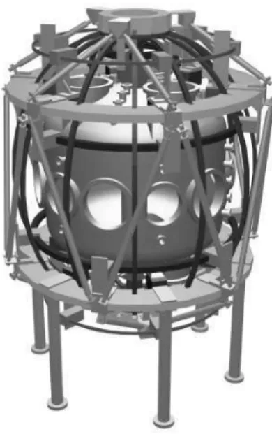
Figure 3. Artistic view of ETE.
It was soon realized the need to include inductive means of plasma current formation to avoid the uncertainties re-lated to the RF methods, and a small solenoid was intro-duced in subsequent versions of the design [24][25][26]. Even at the present time, many of the RF schemes have not been properly tested in spherical tokamaks. In partic-ular, the plasma heating and current drive method based on EBW remains one of the interesting possibilities in the fu-ture [18]. Lacking appropriate financial support for a large size machine, a minimal design for a spherical tokamak was completed in 1993 [27] leading to the present ETE device, which is illustrated in Figure 3. The detailed engineering design was then carried out, with manufacturing of some components beginning in mid 1995 [28][29][30]. Assembly began in mid 1998 after completion of the new experimen-tal hall built at INPE [31]. Tests of the machine started in late 1999 and the first tokamak plasma was attained in 28 November 2000 [32].
4
Research program of ETE
The experimental program of ETE focuses on the study of the physics of spherical tokamak plasmas. The program started with plasmas in the ohmic regime, optimized by good vacuum conditioning and pre-ionization. Adequate control of the particle recycling conditions at the edge will be crucial for a low impurity discharge. An operation parameters space study will be carried out, looking for high-density limits and lowest ratio of the central column current to plasma current. The implementation of a fast neutral lithium beam probe and an array of electrostatic probes will allow a detailed study of the plasma edge conditions. This is an important issue, since it is presently accepted that the plasma boundary processes have a strong influence on the core plasma behavior. Mag-netic activity will be monitored during the entire research program.
The plasma diagnostic system of ETE also includes the basic electromagnetic diagnostics, optical spectroscopy, op-tical imaging and Thomson scattering, already installed, and a far infrared laser interferometry system in the near fu-ture. Soft X-rays imaging in three planes will be attempted in order to estimate the position of the magnetic axis and the elongation at the axis, which should improve the results of the magnetic reconstruction procedure, still to be imple-mented.
By increasing the available capacitor banks the plasma current can be extended from the presently attainable 0.2 MA range to more than 0.4 MA with a 50 ms pulse dura-tion (limited by solenoid stress and heating). The maximum allowable value of the magnetic field is 0.8 T (mechanical stress limit), depending also on an upgrade of the capacitor banks. Means of auxiliary heating and current drive, which will lead to studies of improved plasma confinement, have been just recently addressed, in collaboration with the Uni-versity of S˜ao Paulo in the area of radio frequency plasma heating. Auxiliary heating and current drive is envisaged up to the 1 MW level.
Theoretical work has been carried out during the last few years notably in the areas of self-consistent equilibrium calculations including neo-classical effects, plasma start-up models including eddy current effects, and – looking to ap-plications of high-power microwave sources in ETE – prop-agation and interaction of intense electron beams with radio frequency fields in resonant cavities and corrugated wave-guides. Modelling of the scrape-off layer and studies of the plasma edge physics will be undertaken in the near future.
In general terms, the objective of the ETE experiment is to explore the physics of plasmas in the spherical torus geometry. In particular, it is planned to investigate aspects of the plasma edge physics and the physics of plasma heat-ing by radio frequency waves. Besides research in low as-pect ratio tokamaks and diagnostics development, another important objective of the ETE program is training in toka-mak operation. The ETE tokatoka-mak is open to collaboration with other laboratories and universities, both national and international, providing the only spherical tokamak facility available for training in the southern hemisphere.
5
Technical characteristics of ETE
The main parameters of ETE are listed in Table 2. During the initial operation a modestly high plasma currentIp ∼=
0.2 MA (∼15 ms) will be produced in a 1.5 aspect ratio configuration with a toroidal fieldB0 ≤0.4 T (∼100 ms).
solenoid (∼0.25 Wb,∼180 ms). The design of ETE incor-porates some innovative technological features that resulted in a compact and light weighted device with good plasma accessibility. In the following sections some of the technical characteristics of the main components of the tokamak will be described.
Table 2. Main parameters of the ETE tokamak.
First phase Upgrade
Major radiusR0 0.30 m -Minor radiusa 0.20 m
-Elongationκ 1.6 1.8
Triangularityδ ∼0.3 -Toroidal inductionB0 0.4 T <0.8 T Plasma currentIp 0.2 MA 0.4 MA
V.1 Vacuum system
Figure 4 shows a drawing of the vacuum chamber of the ETE tokamak. It is manufactured from Inconel 625 alloy. The relatively high resistivity of Inconel helps to weaken the eddy current effects in the continuous vessel. The thickness of the inner cylindrical wall is 1 mm and the thickness of the torispherical heads and outer cylindrical wall is 6.35 mm. The internal diameter of the vessel is 0.178 m, the external diameter is 1.219 m and the height is 1.200 m. The inner cylindrical wall of the vacuum vessel can be removed by grinding and replaced by a smaller diameter tube with the re-moval of the ohmic heating solenoid. In this way the aspect ratio of ETE can be reduced from 1.5 to 1.3, if necessary in the future.
Standard ConFlat flanges are used so that adequate bak-ing and discharge cleanbak-ing up to 200◦C can been
imple-mented. Short bellows were roll-formed at the extremities of the inner cylindrical wall in order to reduce the ther-mal stresses during baking. The flanges are distributed around the vacuum chamber in the following configuration: 6×14CF and 4×250CF lateral ports, 3×14CF upward fac-ing ports, 3×14CF downward facing ports and 42×40CF small flanges. Several supports welded in the inner wall of the vacuum chamber are used to install rail limiters and diag-nostics. The vacuum system consists of a 1500ℓ/s turbodrag pump backed by a 4 m3
/h diaphragm pump, plus a 30 m3
/h rotary pump for maintenance procedures, two piezoelectric valves for gas injection (hydrogen, helium, argon, nitrogen) trough a stainless steel line with independent flow and time control, and a residual gas analyzer (RGA). The vacuum chamber is covered by hot tapes for baking (16 kW) and a thermal insulation blanket. A base pressure of 8×10⁻⁸
mbar is easily achieved with baking only up to 110◦C. A butterfly
valve placed in front of the turbodrag pump is used to con-trol the gas flow during glow discharge cleaning (maximum 1 kV/10 A in two symmetrical anodes).
Figure 4. Vacuum chamber of the ETE tokamak.
Electric fields as low as 2 V/m are sufficient for break-down at 2∼3×10⁻⁴
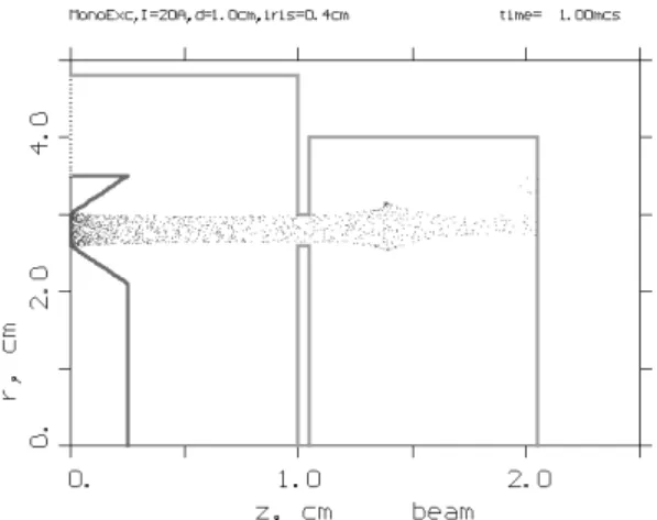
mbar hydrogen pressure with pre-ionization provided by hot filaments (4 A×47 V, 75 V po-larization). Pre-ionization by electron cyclotron resonance heating will be tried in the future to improve the start-up performance of ETE. For this application, a monotron, which is the simplest microwave tube, is under development by the high-power microwave sources group of LAP. The monotron experiment currently under way consists of an electron beam (E0 =10 keV, I0 =20 A) that traverses a
standing-wave cavity resonator (f =6.7 GHz in the mode
T M020) producing 30 kW of output power in the mode
T M01(the electronic efficiency isηelet =0.20 and the
cir-cuit efficiency isηcirc =0.75). Figure 5 shows a
particle-in-cell code simulation of the electron beam bunching inside the cavity. Presently, the prototype electron gun and reso-nant cavity are being characterized.
Figure 5. PIC simulation of the monotron showing bunched elec-tron beam.
V.2 Toroidal field coils
The 12 turns are connected in series by a system of cur-rent feed rings, illustrated in Figure 7, that compensate the stray magnetic field. The height of the TF coil is 1.68 m and the diameter is 1.64 m, leading to a magnetic field ripple< 0.3 % at the plasma edge.
Figure 6. Toroidal field coil of the ETE tokamak.
Figure 7. Exploded view of one turn of the TF coil and of the current feed rings.
Electron beam welding was used in all the fixed joints to maintain the half-hard condition of the 7.3 cm2
cross sec-tion copper bars, which constitute each turn of the coil. The external legs of the TF coil were bend and machined to the bending moment free shape, and the internal legs were ma-chined to their final trapezoidal cross-section. The center stack, with a diameter of 12.4 cm, is water cooled between shots. Since the current density is constant over the length of the coil, each turn is water cooled in its entire length in order to reduce the stress end effects due to temperature vari-ations. Copper tubes with an internal diameter of 5.75 mm were pressed into slots machined in the bars of the TF coil and soft-welded or fixed to each bar for water cooling.
The demountable single bolt joints used in the TF coil are illustrated in Figure 8. Prototypes of these joints were submitted to static stress tests to determine the actual stress limit. Figure 9 shows the stress-strain diagram for the ex-ternal demountable joint. Both the exex-ternal (superposition) and internal (insertion) joints yielded at a stress level equiv-alent to∼1 T magnetic field, as predicted in the design (a 1 T toroidal magnetic field corresponds to a thin-shell torus constant tension of∼28 kN). This result indicates that the operation of the TF coil should be limited to a maximum toroidal field of 0.8 T, to keep a safety margin greater than 50 %.
Figure 8. Single bolt demountable joints of the TF coil.
Figure 9. Stress-strain diagram for the external (superposition) de-mountable joint of the TF coil. Each horizontal division corre-sponds to a displacement of 1 mm and each vertical division to a force increment of 3.07 kN.
V.3 Poloidal field coils
In the design of the ETE tokamak a minimal set of coils was adopted for the poloidal field (PF) coils system, as il-lustrated in Figure 10. It comprises: (1) the plasma magne-tizing coils system, formed by the ohmic heating solenoid in series with two pairs of compensation coils, (2) a pair of equilibrium field coils, and (3) a pair of elongation coils. Ta-ble 3 summarizes the final geometric parameters of the PF coils, measured during the fabrication procedure. The mean radial dimension indicated for the ohmic heating solenoid corresponds to the equivalent radius for an infinitely long solenoid. Some of the coils allow small adjustments in the vertical position, indicated in the column labelled Zrange.
The width (∆R, ∆Z) corresponds to the region filled by
Table 3. Geometrical parameters of the poloidal field coils.
Coil denomination
Ohmic Heating Solenoid Internal Compensation Coils External Compensation Coils
Equilibrium Coils Elongation Coils
R[m] Z[m] Zrange[m]
0.07246 0
-0.1022 ±0.6606 -0.6512 ±0.8797 0.87∼0.96 0.7002 ±0.3900 0.32∼0.45 0.2001 ±0.8300 0.79∼0.87
∆R[m] ∆Z[m] N R×N Z
0.0192 1.3054 2×130 0.021 0.100 2×10 0.010 0.020 1×2 0.040 0.040 4×4 0.040 0.040 4×4
Figure 10. PF coils system of the ETE tokamak.
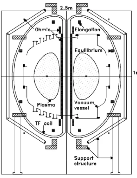
Figure 11. Cross-section of the ETE tokamak.
Figure 12. Magnetizing flux contours on the poloidal plane. The heavy contour indicates a poloidal flux of 0.25Wb (2× 7.8MA-turns in the OH solenoid for double-swing operation) with a2%
increment between contours. The plasma outline, and the vacuum vessel and toroidal field coil centerlines are also displayed.
The position of the PF coils relative to the main compo-nents of the tokamak is shown in Figure 11. The location of all the PF coils was carefully studied to allow good di-agnostic access. The ohmic heating solenoid (OH) fits the narrow gap between the TF coil and the inner wall of the vacuum vessel. In ETE the OH solenoid is formed by two layers of a square cross-section (8.81 mm×8.81 mm), wa-ter cooled hollow conductor (4.93 mm diamewa-ter central hole) and was wound around the central column of the TF mag-net. The remaining PF coils were wound using a slightly different square cross-section (9 mm×9 mm), water cooled hollow conductor (5 mm diameter central hole). All the PF coils are insulated with Kapton, fiberglass tapes and final epoxy resin impregnation. The magnetizing coils system is capable of providing a 0.248 Wb flux variation with double swing operation within the admissible stress limit for half-hard copper, for a maximum current of∼30 kA.
In the initial phase of operation the solenoid will be driven to about half its maximum flux swing capability. In the extended phase the solenoid operation will be limited es-sentially by the maximum adiabatic temperature rise during each shot. The two pairs of passive compensation coils have their location and number of windings optimized to produce, together with the OH solenoid, a minimum error field over a large region near the midplane of the plasma (hexapole field cancellation), as shown in Figure 12. These coils must also be water cooled since they are fabricated with basically the same conductor used in the OH solenoid and are con-nected in series. The remaining two pairs of PF coils supply the time-varying vertical field necessary for plasma position control and for some limited control of the plasma elonga-tion and dispersion of field lines. The central stack (ℓ =
1.87 m, d = 168.8 mm ) was the most challenging piece
V.4 Mechanical structures
Figure 13 shows a drawing of the support structure of the ETE tokamak. It consists basically of two crowns and two rings of insulating material (Tufenol) placed symmetrically with respect to the midplane of the device.
Figure 13. Structure for supporting the vacuum vessel and coils of ETE.
The TF coils are inserted in slots cut in the crowns and rings, which leave the coils free to move in the poloidal plane but resist the out of plane forces. Adjustable stain-less steel rods, manufactured from mechanical tubes, con-nect the crowns and rings, forming a rigid truss structure. The PF coils are attached to the crowns and rings by simple L-shaped supports and clamps, which allow some control of the coils position. The vacuum vessel is placed on plastic shock absorber blocks attached to the support legs and to the upper and lower rings.
The entire assembly is modular and allows very good ac-cess for diagnostics. Simple engineering calculations show that the structure is capable to resist the normal and fault electromagnetic loads, but a more careful analysis is nec-essary to assess the operating limits of the TF coil (B0 ≤
0.8 T) and the structural response of the vacuum vessel to the dynamic forces during a large plasma disruption. The sup-port structure is mounted on a strong aluminum sustentation structure (with toroidal break), which is fixed to a concrete block on the ground level of the tokamak laboratory, giv-ing access to the capacitor banks, power supplies and wa-ter cooling equipment. All the mechanical structures have been fabricated in the Institute’s workshop, and have been assembled and adjusted in the tokamak hall with an overall precision of 2 mm.
V.5 Power supplies
The power supplies system for ETE is based entirely on capacitor banks for energy storage. There are four indepen-dent banks: toroidal, magnetizing, equilibrium and elonga-tion.
The toroidal capacitor bank has a total energy of 1.13 MJ and is designed to supply a current of∼50 kA to the toroidal field coil during about 100 ms, producing a magnetic field of
∼0.4 T with±1% fluctuations. Low voltage electrolytic ca-pacitors, high current thyristors and diodes are used in a two modules configuration: fast bank (1.25 kV, 309 kJ) and slow bank (360 V, 821 kJ fired sequentially in 8 stages). Figure 14 shows the current waveform in the toroidal field coil, ob-tained by numerical simulation.
Figure 14. Current waveform in the TF coil, obtained by numerical simulation.
The magnetizing bank or ohmic heating bank has a total energy of 988 kJ and is designed for double swing opera-tion. This bank uses high voltage oil capacitors, ignitrons and diodes in three modules: charge (8 kV, 467 kJ), start-up (8 kV, 296 kJ) and flattop (7.5 kV, 225 kJ, presently fired in 2 stages). In this configuration the magnetizing bank has the capability of driving and maintaining a plasma current of
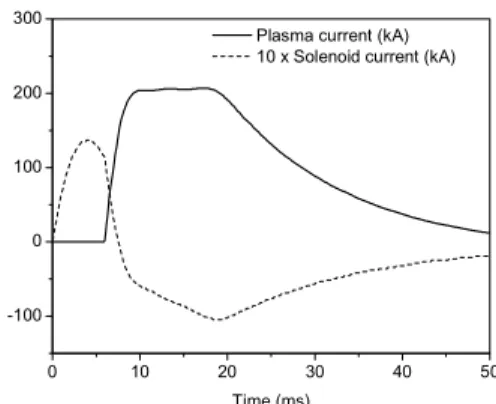
∼200kA during 15 ms. Figure 15 shows the current wave-forms in the plasma and in the double swing OH solenoid, obtained by numerical simulation.
Figure 15. Waveforms of the current in the plasma and 10 times the current in the double swing OH solenoid, obtained by numeri-cal simulation.
bank (360 V, 50 kJ fired in 5 stages), which use an ignitron triggering circuit and thyristor triggering circuits, respec-tively. The capacitor bank is designed to supply a current of∼6 kA during 25 ms to the equilibrium field coils. The elongation bank is still in the design phase since its imple-mentation is not essential during the initial operation of the tokamak.
All activities involving the reconditioning and testing of (mostly secondhand) capacitor banks, fabrication of support structures, and development of triggering and safety circuits used in ETE were conducted by the electronics workshop of LAP. Presently, the energy of the capacitor banks is being continuously increased by adding more capacitor modules as well as by rising the voltage rating to its maximum to reach the first operational phase listed in Table 2.
The magnetizing bank is being provisionally operated in low energy single polarity mode while the effects of eddy currents induced on the vacuum vessel are evaluated and compensation for error fields in the start-up phase is intro-duced. With this low energy configuration the plasma cur-rent is limited to the 40 to 60 kA range corresponding to a pulse duration in the 8 to 5 ms range (12 ms with glow discharge cleaning). Figure 16 shows the evolution of the plasma current in various phases during the operation of ETE.
Figure 16. Evolution of the plasma current in various phases during the operation of ETE.
V.6 Control and data acquisition systems
The ETE tokamak is computer operated with an elec-tropneumatic safety system and complete galvanic insula-tion. The control is based on CAMAC modules and data ac-quisition on a VME bus standard. An optical link provides an insulation of 2 kV (15 kV in the near future) between the control computer and the CAMAC modules. The galvanic insulation between the CAMAC crate and the hazardous en-vironment is achieved by optical and pneumatic systems. All the components of the control system, including trig-gering circuits and pneumatic actuators, are functional and the control software is under continuous development using the C language and HTML interfaces. The VME modules will be introduced progressively with the installation of the diagnostic systems.
V.7 Diagnostic systems
A complete set of fundamental diagnostics is planned for ETE. Table 4 lists the diagnostics proposed for imple-mentation during the initial (inductive) phase of operation, together with the plasma parameters to be measured.
Table 4. Plasma diagnostics to be installed in ETE.
Diagnostic
Magnetics Hαdetectors, bolometers
Hard X-ray monitors Optical spectrometers Thomson scattering
Fast CCD camera Electrostatic probes Low-energy lithium beam probe Far infrared laser interferometer Arrays of soft X-ray diodes
Plasma Parameters
Magnetic reconstruction, magnetic activity Radiated power
Fast electrons, magnetic activity Electron temperature and impurities Electron temperature and density profiles
Optical imaging Plasma edge parameters Plasma edge parameters
Integrated density Electron temperature imaging
An initial set of electromagnetic diagnostics is already installed, comprising: three Rogowski coils to measure the currents in the toroidal, equilibrium and ohmic circuits, one Rogowski coil placed inside the vessel to measure the plasma current and a second one outside the vessel to mea-sure the induced eddy current, twelve loop voltage coils in different positions (one placed inside the vessel), four fixed magnetic pickup coils (Br,Bz) protected by the graphite limiter for magnetohydrodynamic and magnetic field mea-surements, two movable magnetic pickup coils (Br, Bz and Bφ) at the midplane, and one movable electrostatic probe also at the midplane. A visible light spectrometer (12 ˚A/mm) for impurity emission detection and anHα de-tector with interference filter (∆λ =13.52 nm) have been
installed. An hard X-ray detector is being used to map the radiation pattern around the machine. One fast CCD camera with speed up to 500 FPS and frame velocity up to 1/10,000 has been used on loan. Figs 17 and 18 show the time pro-files of the plasma current, loop voltage, vacuum vessel cur-rent, vertical component of the magnetic field at the inboard side of the torus (R=0.0925 m,Z=-0.010 m),Hαlight
Figure 17. Plasma current, loop voltage and vacuum vessel current for a typical discharge in ETE.
α
Figure 18.Bzcomponent at the inboard side of the torus,Hαlight andCI I Iradiation for a typical discharge in ETE.
The plasma current, loop voltage andHα signals show the occurrence of small internal reconnection events that are typical in the operation of low aspect ratio tokamaks. The current induced in the continuous vacuum vessel is quite high. This is a common feature of most spherical tokamaks, but the eddy current distribution has been measured for the first time in ETE. The measured values compare very well with calculations based on a theoretical model [33]. The problem with eddy currents is less severe in devices like START and MAST that have the poloidal coils mounted inside a large vacuum vessel, but this implies that there is no passive wall stabilization and a very peculiar condition of particle fuelling due to the large volume of the vacuum chamber compared to the plasma volume. In the SUNIST device it is planned to verify the full effect of vessel eddy currents on the plasma discharge with the installation of an elaborate insulating break [16]. Another aspect of the eddy currents is that they affect the magnetic measurements. For example, the loop voltage signal shown in Figure 17 has a large contribution from the current induced in the vessel. Notice that near t = 5ms the signal goes through zero,
when the induced current also changes its sign and opposes the drop in the plasma current. Presently, methods are being developed to take into account this contribution.
A Thomson scattering system consisting of a 10 J, 20 ns Q-switched ruby laser, a 5-channels polychromator filter with avalanche photodiodes, and collecting lenses capable
of scanning 22 different plasma positions along 50 cm of the laser beam trajectory at the midplane is operational. In the initial tests, plasma temperatures ranging from 20 to 160 eV and densities up to 0.4×10²⁰m−3 have been measured in
hydrogen discharges with plasma current of 60 kA ampli-tude and 5 ms duration [34]. The highest values obtained for the temperature are consistent with the smallest values of theHαradiation andCIIIimpurity. Figs. 19 and 20 show the radial distributions of the electron temperature and the plasma density, respectively, measured 4 ms after the start of a typical discharge in ETE. The present single channel Thomson scattering system will be gradually upgraded to obtain complete electron temperature and density profiles during each shot. For this purpose, a multipoint operation method using a time-delay technique based on optical fibers of different lengths is being developed.
Figure 19. Radial distribution of the electron temperature 4 ms af-ter the start of the discharge in ETE.
Figure 20. Radial distribution of the plasma density 4 ms after the start of the discharge in ETE.
A 10 kV fast neutral lithium beam (FNLB) probe with glassy β-eucryptite source (up to 1 mA/cm2
Design of a multipass Michelson interferometer system has been recently completed. This system uses a 50 W CO2
laser (λCO2=10.6µm) and a 20 mW HeNe laser (λHeN e=
0.6328µm). The CO2 laser is injected in the tokamak
through a set of flat mirrors and is kept in the plasma by multiple reflections between two spherical mirrors (R =
1.5 m). Simulations indicate that it is possible to have 22 passages through the plasma, which correspond to more than two fringes of wavelength shift considering a plasma length of 60 cm and peak density 0.5×10²⁰m−3. The HeNe laser
will be used for alignment purposes and to eliminate errors due to mechanical vibration of the system. An array of soft X-ray diodes, which is in the design phase, will be used to produce images of the temperature in three planes, provid-ing additional information for the magnetic reconstruction procedure, still to be developed.
V.8 Infrastructure
The main building for ETE was finished in mid 1998. The installations comprise: the tokamak hall (150 m2
con-taining a 2 ton crane and a 800 kg lift), the power supplies area (225 m2
for the capacitors banks), the control room (35 m2
), the engineering and physics room (30 m2
), the computer room (18 m2
), the support systems area (50 m2
re-served for the water cooling system - 10 bar, 6 m3
/h, 6-20◦C
- and the dry compressed air system - 7 bar, 0.5 m3/min),
the electrical supply room (50m2 containing transformers
with ultra insulation - 450 kVA, plus transformers with stan-dard insulation - 300 kVA). Finally, the ETE workshop, with 250 m2
in two stories, is used for the fabrication of coils and mechanical parts plus the development of electronic circuits.
Acknowledgments
The construction of ETE was partially supported by the Studies and Projects Funding Body (FINEP) and the State of S˜ao Paulo Research Foundation (FAPESP). One of the authors (G.O.L.) thanks the International Atomic Energy Agency (IAEA) for financial support to ETE related activi-ties through research contract BRA-10528.
References
[1] Y-K. M. Peng and D.J. Strickler. “Features of spherical torus plasmas”. Nuclear Fusion,26(6), 769 (1986).
[2] H. Bruhns, R. Brendel, G. Raupp, and J. Steiger. “Study of the low aspect ratio limit tokamak in the Heidelberg sphero-mak experiment”. Nuclear Fusion,27(12), 2178 (1987).
[3] G.A. Collins, G. Durance, G.R. Hogg, J. Tendys, and P.A. Watterson. “Small aspect ratio tokamak configurations gen-erated by rotating magnetic field current drive”. Nuclear Fu-sion,28(2), 255 (1988).
[4] P.K. Browning, G. Cunningham, R. Duck, S.J. Gee, K.J. Gib-son, D.A. KitGib-son, R. Martin, and M.G. Rusbridge. “Injection and sustainment of plasma in a preexisting toroidal field us-ing a coaxial helicity source”. Physical Review Letters,68
(11), 1722 (1992).
[5] E. Del Bosco, R.J. Colchin, G. Cunningham, et al. “Results from the START tokamak”. Proceedings of the 1o
Congresso Brasileiro de F´ısica dos Plasmas, Vol. I - Invited Papers: 212-227. INPE, S˜ao Jos´e dos Campos, 1991.
[6] A. Sykes, E. Del Bosco, R.J. Colchin, et al. “First results from the START experiment”. Nuclear Fusion,32(4), 694 (1992). [7] A. Sykes and the START, NBI, MAST and Theory Teams. “The spherical tokamak programme at Culham”. Nuclear Fu-sion,39(9Y), 1271 (1999).
[8] T. Maekawa, H. Tanaka, M. Uchida, et al. “Start-up and for-mation of ST plasmas by ECH on the LATE device”. 19th Fu-sion Energy Conference, Lyon, France, 2002. Paper EX/P4-16, IAEA, Vienna, 2002.
[9] R. Kaita, R. Majeski, R. Doerner, et al. “Liquid lithium lim-iter effects on tokamak plasmas and plasma-liquid surface in-teractions”. 19th Fusion Energy Conference, Lyon, France, 2002. Paper EX/P4-19, IAEA, Vienna, 2002.
[10] Y. Ono, T. Kimura, E.Kawamori, et al. “High-beta charac-teristics of first and second-stable spherical tokamaks in re-connection heating experiments of TS-3”. Nuclear Fusion43, 789 (2003).
[11] F. Alladio, A. Mancuso, P. Micozzi, et al. “PROTO-SPHERA”. Report RT/ERG/FUS/2001/14, ENEA Centro Ricerche Frascati, Rome, Italy, 2001.
[12] A.J. Redd, B.A. Nelson, T.R. Jarboe, et al. “Current drive ex-periments in the helicity injected torus (HIT-II)”. Physics of Plasmas,9(5), 2006 (2002).
[13] M. Nagata, T. Oguro, Y. Kagei, et al. “Coaxial helicity injec-tion and n=1 relaxainjec-tion activity in the HIST spherical torus”. 19th Fusion Energy Conference, Lyon, France, 2002. Paper EX/P4-17, IAEA, Vienna, 2002.
[14] R.J. Fonck, G. Garstka, S. Diem, et al. “Performance and sta-bility limits at near-unity aspect ratio in the Pegasus toroidal experiment”. 19th Fusion Energy Conference, Lyon, France, 2002. Paper EX/P3-09, IAEA, Vienna, 2002.
[15] A. Ejiri, S. Shiraiwa, Y. Takase, et al. “Ion temperature in-crease during MHD events on the TST-2 spherical tokamak”. 19th Fusion Energy Conference, Lyon, France, 2002. Paper EX/P4-10, IAEA, Vienna, 2002.
[16] Y. He. “Research program of spherical tokamak in China”. Proceedings of the Joint Meeting of the 2nd International Atomic Energy Agency Technical Committee Meeting on Spherical Tori and the 7th International Spherical Torus Workshop, INPE, S˜ao Jos´e dos Campos, SP, Brazil, 2001. [17] V.K. Gusev, A.S. Ananiev, I.N. Chugunov, et al. “New
re-sults from Globus-M spherical tokamak”. 19th Fusion Energy Conference, Lyon, France, 2002. Paper EX/P3-10, IAEA, Vi-enna, 2002.
[18] A. Sykes. “Overview of recent spherical tokamak results”. Plasma Physics and Controlled Fusion,43, A127 (2001). [19] B. Lloyd for the MAST team. “Overview of recent
experi-mental results on MAST”. 19th Fusion Energy Conference, Lyon, France, 2002. Paper OV/2-3, IAEA, Vienna, 2002. [20] R. Maingi et al. “Recent results from the National Spherical
Torus Experiment”. Plasma Physics and Controlled Fusion,
45, 657 (2003).
[22] R.M.O. Galv˜ao, L.C.S. G´oes, G.O. Ludwig, A. Montes, and M. Ueda. “Conceptual design of a radio frequency driven compact tokamak”. In P.H. Sakanaka (ed.),Fusion Energy and Plasma Physics, Proceedings of the First Energy Inde-pendence Conference, pp. 471-483. World Scientific, Singa-pore (ISBN-9971-50-749-8) 1988.
[23] D.C. Robinson. “First Energy Independence Conference: Fu-sion Energy and Plasma Physics”. Nuclear FuFu-sion,28(2), 331 (1988).
[24] G.O. Ludwig, A. Montes, and P.H. Sakanaka. “Preliminary design of a small aspect ratio tokamak”. Research Using Small Tokamaks, Proceedings of the IAEA Technical Com-mittee Meeting on Research using Small Tokamaks, Nice, France, 1988. IAEA Technical Document 519: 111-123, Vi-enna, 1989.
[25] G.O. Ludwig, Y. Aso, J.J. Barroso, J.L. Ferreira, R.M.O. Galv˜ao, A. Montes, G.M. Sandonato, M. Ueda, W.P. S´a, A.G. Tuszel, and L.C.S. G´oes. “The Proto-ETA small aspect ra-tio experiment”.Improving Tokamak Performance through Innovations from Small Fusion Experiments, Proceedings of the IAEA Technical Committee Meeting on Research using Small Tokamaks, Washington, USA, 1990. IAEA Technical Document 604: 159-174, Vienna, 1991.
[26] G.O. Ludwig and A. Montes. “Plasma performance of low aspect ratio tokamaks - the TBR-E experiment”. Proceedings of the 1o
Congresso Brasileiro de F´ısica dos Plasmas, Vol. I, Invited Papers: 332-345. INPE, S˜ao Jos´e dos Campos, 1991. [27] G.O. Ludwig. “Anteprojeto de engenharia do tokamak ETE”. INPE report 5529-PRE/1796 (in Portuguese), INPE, S˜ao Jos´e dos Campos, 1993.
[28] G.O. Ludwig. “Theoretical methods in the design of the poloidal field coils for the ETE spherical tokamak”, Brazil-ian Journal of Physics27(3), 392 (1997).
[29] G.O. Ludwig, L.F.W. Barbosa, E. Del Bosco, et al. “The Brazilian Spherical Tokamak Experiment”. Proceedings of the 3o
Encontro Brasileiro de F´ısica dos Plasmas: 128-131. INPE, S˜ao Jos´e dos Campos, 1995.
[30] E. Del Bosco, G.O. Ludwig, J.G. Ferreira, et al. “The ETE spherical tokamak: present status of construction”. Proceed-ings of the 4o
Encontro Brasileiro de F´ısica dos Plasmas: 24-27. INPE, S˜ao Jos´e dos Campos, 1996.
[31] E. Del Bosco, G.O. Ludwig, A. Montes, et al. “Status of con-struction of the ETE spherical tokamak”. Proceedings of the 5o
Encontro Brasileiro de F´ısica dos Plasmas: 277-280. SBF, S˜ao Paulo, 1998.
[32] G.O. Ludwig, E. Del Bosco, J.G. Ferreira, et al. “First results of the ETE spherical torus”. Abstracts of the 6o
Encontro Brasileiro de F´ısica dos Plasmas, Invited Paper: 53 , Cam-pos do Jord˜ao, SP, 2001.
[33] G.O. Ludwig. “Calculation of eddy currents in the ETE spherical torus”. In I.S. Falconer, R.L. Dewar and J. Khachan (eds.), Proceedings of the Eleventh International Congress on Plasma Physics, AIP Conference Proceedings669: 573-576 (ISBN 0-7354-0133-0) 2003.