Abstract— The concern about the health risks that wireless technology can provide has grown globally thanks to the growing use of the devices by the population, by the finding that the public exposure to EMFs from the devices can be enhanced by the reflection of the microwave indoors. This paper will assess the distribution of electromagnetic field in a car, in order to provide a basis for future research and to estimate the actual level of exposure to which humans are submitted. There were a number of electrical measurements to determine the electromagnetic field produced by various electromagnetic sources. From the results observed, it is possible to see that, in a car, the exposure of humans to EMF is intensified by the reflection of electromagnetic waves in metallic structures. The observed values do not exceed the values recommended by the regulation, but in the face of scientific uncertainty on this issue, is motivated to continue studying the effect of the reflection of microwaves in closed environments, in order to investigate the possible impacts on health.
Index Terms— electromagnetic field, electromagnetic sources, monopole antennas, quasi-isotropic antenna, reverberation chamber.
I. INTRODUCTION
From the beginning of his existence, man has been subject to risks. With this, the demand for
remedying these risks led him to evolve as seeking ways to improve their safety and well-being. With
the modernization of production processes and therefore increase the division of labor, the dangers to
which man faces in society have undergone a series of changes and, depending on the occupation,
socioeconomic status and place of residence, it is a lesser or greater security. Nevertheless, natural
phenomena still occur unexpectedly, and even cultural and technical advancement has made the
company spend to live, even with risks caused or exacerbated by the use of technologies [1].
Electromagnetic fields are produced by different sources, natural or artificial. In the last hundred
years, the artificially generated electromagnetic fields have increased with the widespread use of radio
transmission equipment and electricity, which are key elements in industrialized societies. In contrast
to technological advances, the suspicion that electromagnetic fields can bring health risks has led to
Measurement with Quasi
-
Isotropic
Antenna of CEM Coming from Multisource in
a Reverberation Chamber and in a Car
Raquel Aline A. Rodrigues, Glauco Fontgalland, Galba F. Aragão, Felipe C. Lins
Federal University of Campina Grande, Street Aprígio Veloso, 882, Bairro Universitário, Campina Grande, Paraíba- Brazil, CEP 58.429-900
e-mail: [email protected], [email protected], [email protected],
several studies since the 1970s [1].
Given the skyrocketing use of RF equipment for a large portion of the population has also grown
the concern of users, government authorities and the scientific community regarding the health risks
that this technology can provide.
This concern is motivated mainly by the fact that, although known carcinogenic effects due to
exposure to ionizing radiation and thermal effects, acute and short-lived due to exposure to
ionizing radiation, there is no agreement on the thermal effects in long-term generated
non-ionizing radiation. In them are included stationary magnetic fields, extremely low frequency fields,
radio (microwave), infrared, ultraviolet, visible light and sound fields as ultrasound and infrasound
[2].
Some studies report that public exposure to EMF from RF sources can be enhanced by the
reflection of microwave indoors, these places include elevators, buses, trains and cars. This paper will
evaluate the distribution of electromagnetic field in a car, in order to provide input for future research
in order to estimate the actual level of exposure to which humans are exposed (children, adults and
old), because of the limitations on technology field measurement inside the human body, it is
necessary at least to provide data with respect to the levels to which humans are exposed. Such
information can be valuable to the choice of purchasing a vehicle, for example, or restriction of use
within the same that is with full capacity (packed vehicle).
II. ELECTROMAGNETIC WAVES AND MECHANISMS OF INTERACTION WITH THE HUMAN BODY
The electromagnetic waves used in mobile communications is the vehicle of energy transported
through space in the form of electric and magnetic fields varying with time. Typical examples of
electromagnetic waves include radio waves, TV signals, the radar beams and rays of light. All forms
of EM waves share three main characteristics: they all travel at high speeds, to propagate, exhibit
wave properties and they are radiated from a source without the need for a physical means of
propagation [3].
With increasing frequency, electromagnetic wave energy becomes more concentrated, making it
necessary to make a distinction between radio frequency waves that are in the range of non-ionizing
radiation, and waves of higher frequencies, which are in the range of ionizing radiation.
The object of this paper is non-ionizing radiation in the range of radio frequencies used by mobile
transceivers to transmit (in the far field region).
Electromagnetic waves when they interact with the human body, depending on the frequency and
power, may produce some biological effect. This fact alone does not necessarily mean the existence of
danger. A biological effect will become a security risk when a fault occurs in a person’s health or their
descendants [2].
The consequences of the mechanisms of interaction of non-ionizing electromagnetic waves with
• Thermal effects: are caused by tissue heating as a result of absorption of part of the incident wave; • Non-thermal Effects: are due to direct interaction of electromagnetic fields induced in the body.
III. MATERIAL AND METHODS
A. Technical Standards Adopted
The regulation adopted in Brazil by the National Telecommunications Agency - ANATEL
Resolution No. 303 of July 2, 2002, for the assessment of human exposure to electromagnetic fields
from radio from transmitting stations of telecommunication services [4], has reference to the limits
proposed by International Commission for Non-Ionizing Radiation Protection, ICNIRP.
The exposure limits established in the regulations refer to occupational exposure and exposure of
the general population to electromagnetic field of radio frequency in the frequency range between 9
KHz and 300 GHz. As in this research study in the closed environment fits the scenario of exposure
not controlled by the general population and the sources of electromagnetic field in the operating
frequency of 2.047GHz, it will be adopted as the threshold values for display only those presented in
Table 1 [4].
TABLE 1. LIMITS FOR OCCUPATIONAL EXPOSURE TO ELECTRIC, MAGNETIC AND ELECTROMAGNETIC FIELDS IN THE RADIO FREQUENCY BETWEEN 2 GHz AND 300 GHz (UNPERTURBED EFFECTIVE VALUES)
Frequency Range Eletric Field E (V/M)
Magnetic Field H (A/M)
Equivalent Plane-Wave Power Density S (W/m2)
2 GHz to 300 GHz 61 0.16 10
B. The Electromagnetic Environment Been Researched
Among the global trends, the growing demand for information and communication has created the
need for use of various sources of non-ionizing electromagnetic waves such as cell phones, iphones,
bluetooth and tablets. In modern cars, besides the increase in the number of electric and electronic
devices in the constitution (electronic panels, system lock brakes (ABS), airbags, fuel control, alarm,
global positioning system (GPS) and electronic fuel injection, between others) can be found several
types of RF sources inside the same as TV, cell phones, laptops, palmtops, notetaker and netbooks [5].
In the near future, due to increasing demand for security, protection and sustainable mobility, the
cars will be equipped with automatic warning systems to avoid accidents and also for emergency
calls, thereby increasing the number of sources of electromagnetic field that will be introduced in
these environments. Moreover, it will be present in electric cars low frequency fields.
Thus, in an environment almost closed of the automobile, various propagation phenomena occur:
the sources of RF can behave as an antenna array increasing the gain in a given direction, the metal
structure of the car favors the reverberation of electromagnetic fields in inside generating constructive
and destructive combinations of fields; reflections internal structures of the vehicle, and the presence
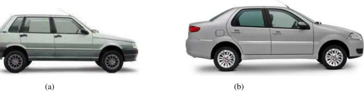
The electromagnetic environment of a vehicle is defined by values and electrical quantities such as
voltages and currents in conductors or electromagnetic fields in space, a result of electromagnetic
phenomena that are present and involve the automobile, as shown in Figure 1 [5].
(a) (b)
Fig. 1. Almost closed environment under study: (a) compact car and (b) sedan car
Basically a car may be considered as a rectangular resonant cavity. Ideally, the field taken at any
point of the interior of the cavity is the sum of standing waves existing due to multiple reflections [6].
Within environments with metallic walls, such as an automobile for example, the existence of one
or more occupants disturbs the distribution of the microwave, which usually decreases the absorption
intensity, but may increase the intensity of the reflections locations. A study between the two cases
(with and without occupant) showed that the effect of an absorber in the global distribution of
micro-waves is negligible compared to the order of strengthening the intensity of reflection [7].
C. Sources Electromagnetic the Search and Equipment Utilized
In this study were taken as sources of electromagnetic field of the monopole antennas quarter
wavelength operating with vertical and horizontal polarization in the frequency ranges of the UMTS
standard, as Figure 2. The reason for that is that adoption dipoles and monopoles are two types of
antennas commonly used in wireless communication systems.
The Monopole antennas were modeled each by a metal rod of 37.5 mm (diameter 1.8 mm) and
ground plane conductor compose of three rods of 25 mm separated 120° apart. In the next step we
simulated the operation of the antenna with the software MS-CST and checked in the laboratory as
per Figures 3 and 4.
Each monopole antenna was listed for identification, fed with power of 500 mW and individually
calibrated and tested scattering parameters, standing wave ratio (SWR) and The Smith Chart, so that
these could be considered approximately equal. We also measured the reception levels of monopole
antennas and antenna measurement (log-periodic) for maximum 1.20m and minimum 81cm distances
among those inside the car, these measurements were taken in the far field antenna measurement
previously calculated.
In the calibration procedure and measuring monopole antenna characteristics, measurement of
losses in cables used in monopole antennas and reception, measurement the impedance of the
receiving antenna and measures the power inside the cars and the reverberation chamber were used: a
signal generator Rohde & Schwarz model 5M300 coupled via coaxial cable (RG58 C / U of 1.45 m)
coupled via coaxial cable (cable HFU2) to the receiving antenna-dipole double arc and a spectrum
analyzer Agilent N1996A CSA- that was also connected to the receive antenna.
(a) (b)
Fig.2- (a) Project monopole antenna for the frequency range from 1.8 to 2.1 GHz with simulated software CST, (b) Photos of the monopole antennas built-in LEMA Laboratory of Applied Electromagnetics and Microwave-DEE / LEMA / UFCG.
(a) (b)
(c) (d) (e)
Fig. 4- Diagrams 3D of radiation monopole antenna simulated in the software CST.
Due to the ground plane of each monopole constructed not be continuous (as radial were used) and
the radial be finite in length, was found not to occur in symmetrical radiation pattern as expected for a
monopole with infinite ground plane (or almost infinite) and solid that behaves as an isotropic
radiation source as shown in Figure 5. Thus, it was verified through measurements of power around
each monopole in operation, the regions with maximum power emitted radiation for each monopole.
(a) (b)
Fig. 5- (a) Monopole antenna with ground plane almost infinite, (b) Diagrams 3D and 2D of radiation monopole antenna
simulated in the software CST for (a): ground plane almost infinite.
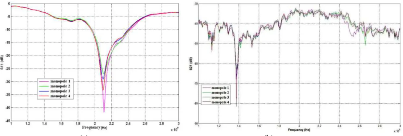
In Figure 6 are compared with the values of the scattering parameters S11 and S21 respectively to
the four monopole antennas. The values of S21 were measured with the log-periodic antenna Rohde
& Schwarz input impedance Z = (47 + j7, 8) Ω, coupled via coaxial cable to the analyzer mesh ENA
Series Network Analyzer Agilent E5062A in the frequency range from 1 to 3 GHz.
You can see that the four antennas resonate satisfactorily in the frequency of 2.1 GHz through
graphs of the reflection coefficient S11. The same frequency is also observed that the level of transmit
power is satisfactory for all antennas by the responses of the transmission coefficient S21 for each
(a) (b)
Fig.6- (a) Scattering parameter S11 of the four monopole antennas, (b) Scattering parameter S21 of the four monopole antennas.
D. The Far-field
The measures of this study were conducted in the region of the distant fields of monopole antennas determined from the following conditions [8]:
(1.1)
(1.2)
(1.3)
Where:
r = distance from the antenna to the far field [m];
D= dimension of the antenna elements [m];
λ = wavelength in the operating frequency [m];
Substituting λ =0.143 and D = λ /4 = 0.036m (at 2.1GHz) comes to air = 22.4 cm.
E. Antenna Measurement- Dipole Double Arch
The antenna measurement used in the experiments with reverberation chamber and in interior of the
automobiles was the dipole double arc, with input impedance Z= (53.8 + j46.3) and antenna factor of
44.2 dB produced by Edvaldo Silva Pires in his Masters in UFCG. This antenna is designed to radiate
uniformly two polarizations in the three perpendicular planes. The format and dimensions for the
geometry of the dipole double arc are shown in Figure 7 [9].
Figure 2 - Dipole Double arch built in LEMA/DEE/UFCG and its dimensions in wavelength.
With this configuration the antenna radiates and receives energy in two linear polarizations in all
three axes. Each arm antenna has ¼ the wavelength. This antenna was built to radiate at a frequency
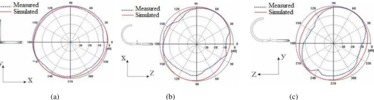
The irradiation diagrams of the dipole double arch have characteristics close to isotropic radiator as
are shown in Figure 8.
(a) (b) (c)
Fig. 8- Radiation pattern of the dipole double arch: (a) YX plane, (b) XZ plane and (c) ZY plane.
The simulated gain for this antenna, taking as reference isotropic antenna, was 1.849 dB and
directivity stayed in 1.834 dBi in both operating frequency. These values approximate value of ideal
isotropic antenna that is zero dB for gain and directivity. These values reinforce the characteristics of
isotropy of the dipole double arch antenna [9].
F. Experiment Inside the Reverberation Chamber
The goal of this step was to verify the amplification of electromagnetic field generated by monopole antennas in a resonant cavity with dimensions smaller than the dimensions of a car for later
comparison.
A reverberation chamber (CR) is a resonant cavity electrically large and highly conductive (IEC
61000-4-21) that functions as an RF amplifier. It is constructed with an armored jacket inside which
elements are usually positioned agitators modes. Ideally the field taken at any point inside this cavity
is the sum of different standing waves existing due to multiple reflections [10].
The reverberation chamber used for the experiment with the type monopole antennas was
developed by Erik Farias [6]. The walls were made using the same aluminum plate number 18 each
measuring 2x1 m2 as shown in Figure 9.
There is a region within the reverberation chamber in which the electromagnetic field is uniform in
any polarization. To achieve that the field is relatively uniform medium chamber should have a
sufficient number of resonant modes constantly displaced, which is achieved by varying the boundary
conditions within the cavity. These conditions are achieved by changing the characteristics of the
shaker modes, hence the importance of this element [11].
The experimental chamber was performed in two stages: the first stage with two monopole
antennas inserted in the area useful test in the presence of agitators and so the second stage without
the agitators. When using a mobile agitator modes, each variation of its position occurs a change in
the boundary conditions and consequently the resonant modes are also changed, degeneracy of modes
reducing and increasing the uniformity of the field within the chamber.
The antenna used in the measurement chamber has a dipole double arch. We used a signal
generator model 5M300 Rohde & Schwarz and a spectrum analyzer Agilent N1996A-CSA. In Figure
10 are some photos of the measurements inside the chamber of reverberation. The antennas were at
the height of 45cm into the chamber.
Fig. 10- Measurement Environment inside the reverberation chamber: (1) and (2) monopole antennas at a wooden support,
(3)Dipole double arch connected to the spectrum analyzer, (4) Agitators modes,(5) Chamber without the agitators.
G. Experiment inside the Vehicles
At this stage we performed the mapping of Electromagnetic field inside the car. Were performed
measurements of voltage and power of signals from the monopole antennas using as the antenna
measurement dipole double arch.
The monopole antennas were positioned to simulate the height of the mobile device in use by an
adult human being inside two vehicles - a compact car Fiat brand, model Uno Mille Fire Flex 2006
and a sedan Fiat brand, model Siena Fire 2010. The antennas were placed as follows way: an antenna
on the front passenger seat and the other three in the rear seat, as can be seen in Figure 11.
The experiment was conducted with the dipole double arch in five positions: the driver's seat, in the
passenger seat front, in the back seat in the three seats held by passengers. For each position of the
dipole, measurements were made considering sixteen combinations of monopole antennas connected
(in use) or not [12]. Measurements were performed for two steps in each configuration of antennas,
made of voltage and power in various situations inside the two cars. This methodology was adopted in
order to obtain a greater number of measurement points for the mapping of the electromagnetic field
inside the cars, which is observed the influence of the metal structure and constitution of objects
absorbers in the fields.
Pictures within the experimental procedure of driving using the dipole are shown in Figure 12.
Fig. 12- Perspectives outside and inside the cars and positioning monopole antennas created in Rhinoceros software.
Figure 12 - Experiment inside the car with antennas arranged to 1.12 m soil: (1) monopole antenna in the front seat
occupied by the passenger, (2) monopole antennas in the back seat for all three passenger seats, (3) dipole antenna in the
passenger seat and (4) dipole antenna in the back seat in a passenger position.
To calculate the level of electric field inside the cars and reverberation chamber was used
Expression (2) [13], where loss of the cable was considered 2.54 dB for measurements in cars and
1.27 dB for measurements in the chamber.
(2)
Where: E= electric field incident receiving antenna, Vantenna = Voltage at the terminals of the
receiving antenna, AF = antenna factor of the receiving antenna, Pcable= ohmic loss in the cable (dB).
The field values were obtained in dBµV/m for convert them to V/m was used the following
expression [13]:
(3)
In these experiments we found some difficulties and limitations. The first concern was using RF
to measure the intensity of the electric field produced the mobile device since it is variable and
depends on the transmission power. So were made monopole antennas ¼λ to operate similarly to
mobile device, but with fixed power.
The limitation of low power supplied by the generator signals used for feeding RF sources was a
gain offset calculated for the results experimental data.
Further measurements were performed with commercial devices inside the compact car, like a
smartphone and a tablet, together with the monopole antennas. These experiments allowed only an
analysis of the power levels measured for some situations, but it was not possible to calculate the field
inside the car from the monopoles together with these commercial devices because we did not have
the specs of the latter.
Given the limitations on the available devices measurement as to perform the temporal average of
electrical parameters were used along with a spectrum analyzer, antennas available on that LEMA
making possible measurements in the frequency range of signals issued by the RF sources and thus
could be calculated the electromagnetic variables as the restrictions of ANATEL.
Some precautions that should be taken to performing these experiments are: use maximum values
authorized the transmission parameters of the RF sources, perform measurements with equipment
properly calibrated and measurements of electromagnetic fields should be made in absence of
potentially exposed persons [4].
IV. RESULTS
Analysis of the reference field variation with respect to an almost closed environment (car). A
chamber reverberation enables the measurement of total radiated power sources by providing uniform
energy density entire workload. With modest energy sources chamber reaches high field values. Such
requirements are achieved when there is a significant number of modes resonance excited within the
chamber.
The Field Uniform Zone (ZCU), region or volume inside the chamber reverberation that comply
with the limits set by the standard relating to aspects of calibration, which is used in the experiment
has dimensions 55 x 60 x 65 cm3. Due to limitation of these reduced dimensions of the chamber in
relation to the dimensions of an automobile, restricted to the number of monopole antennas within the
closed environment for two antennas because with four antennas together, these would behave like a
kind of arrangement, forming constructive and destructive combinations of field, becoming the region
further than the environment inside the vehicles.
A signal generator Rohde & Schwarz was used to feed the monopole antenna with a power of 1
mW. Then, the power values measured gain was increased so that the input power of each antenna
reaches 500 mW due to the low level signal provided by the signal generator and coupled to cable
attenuation (dB 1.27).
values of power and the electromagnetic field to the measurements performed in the reverberation
chamber.
TABLE 2. VALUES OF THE ELECTROMAGNETIC CONFIGURATIONS FOR FOUR MONOPOLE ANTENNAS
WITHIN A REVERBERATION CHAMBER IN THE PRESENCE OF AGITATOR MODES.
TABLE 3. VALUES OF THE ELECTROMAGNETIC CONFIGURATIONS FOR FOUR MONOPOLE ANTENNAS
WITHIN A REVERBERATION CHAMBER IN THE PRESENCE OF AGITATOR MODES.
In figure 13 is shown the graph that compares the values obtained for the electric field inside the
chamber reverberation with and without agitator modes.
Fig. 13- Comparison of the calculated electric field values for measurements inside the reverberation chamber with and
without agitator modes.
ZCU in a multimode resonant structure of the average value of the magnetic field uniform in all
polarizations, yet the reverberation chamber enables the measurement of total power radiated by
sources and not the electric field at a specific distance. On experiment in question, we measured the
levels of power total irradiated for various configurations of monopole antennas in order to calculate
the electric field at a single point so the closeness of values for situations with and without presence of
the agitator modes.
However, these field values were higher with the presence of the agitator modes within the
chamber in two configurations of the antennas (with only one active antenna each time) and other
settings fields were greater without presence of the agitator, with a considerable difference mainly in
the setup that has two active antennas within the chamber constituting an antenna array to which
modifies the field distribution.
Antenna 2 Antenna 1
1 0 0 -55.71 2.69E-09 0.06
2 0 1 -2.35 0.000582 28.73
3 1 0 -3.26 0.000472 25.88
4 1 1 3.85 0.00243 58.67
Configuration of antennas
With agitator modes
P (dBm) P (W) E (V/m)
Antenna 2 Antenna 1
1 0 0 -53.39 4.58E-09 0.08
2 0 1 -4.35 3.67E-04 22.82
3 1 0 -11.91 6.44E-05 9.56
4 1 1 4.75 2.99E-03 65.07
Configuration of antennas
Without agitator modes
This result is due to the fact that the spreader modes standardize the field and at the moment of
measurement without agitator modes, the field value obtained in a point be less than or greater than
the value of the uniform field provided by the presence of the agitator.
In step mapping the distribution of the electromagnetic field inside the car, measurements were
made of voltage and power values and calculated electric field signals coming from the monopole
antennas.
In sedan car 96 measurements were performed for various configurations of the antennas in two
situations: with the windows open and closed. In the compact car, the results of the experimental
procedure were arranged for two steps measurements performed in two horizontal planes: a height of
1.12 m above the ground simulating the height of a child or smaller adult (plane 1) and 1.26 m soil
simulating the height of an adult (plane 2), totaling 384 measurements.
Table 4 shows the numbers assigned to the various status settings of the antennas inside the car
during measurements [12].
TABLE 4. NUMBER ASSIGNED TO THE VARIOUS SETTINGS STATUS OF ANTENNAS INSIDE THE CAR
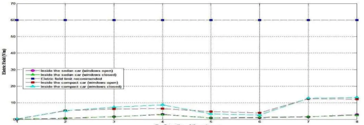
In Figures 14 and 15 are shown comparisons between values obtained with measurements using
log-periodic antenna inside the compact car and the free space [12], measurements using the dipole
double arch in the driver's seat of the compact car for plans 1 and 2 and the limit value for human
exposure to electric fields established by Resolution No. 303 of Anatel of July 2, 2002.
Fig. 14- Comparison between the values of the electric field to sixteen configurations of monopole antennas (placed in the
plane 1) in four situations and limit established by Resolution No. 303 of Anatel.
Antenna 1 Antenna 2 Antenna 3 Antenna 4
1 Off Off Off Off
2 Off Off Off On
3 Off Off On Off
4 Off Off On On
5 Off On Off Off
6 Off On Off On
7 Off On On Off
8 Off On On On
9 On Off Off Off
10 On Off Off On
11 On Off On Off
12 On Off On On
13 On On Off Off
14 On On Off On
15 On On On Off
16 On On On On
Fig. 15- Comparison between the values of the electric field to sixteen configurations of monopole antennas (placed in the
plane 2) in four situations and limit established by Resolution No. 303 of Anatel.
The graph of Figure 14, it is observed that were obtained higher values of electric field
measurements made with the dipole double arch compared with levels obtained using the
log-periodic, this fact should be mainly by the shortest distances between the antennas monopole and
dipole double arch antenna measurement compared to the distances between the monopoles and
log-periodic.
For situations with the windows open and closed with dual dipole arc inside the car, nine settings
field values were obtained with the larger windows closed, which shows the influence of reflections
standing waves due to glass, which add increasing the value of the resulting field inside the
automobile.
The threshold electric field established by Resolution No. 303 of Anatel is much higher than the
values obtained in the situations studied in this step.
The graph of Figure 15, there is again that higher values were obtained in the electric field
measurements taken with the dipole dual arc compared to the levels obtained using the log-periodic
for the same reason described for the experiment in plane 1.
For situations with the windows open and closed with dipole double arch inside the car, in the case
of experiments in the second plane, the field values obtained for the two situations-with windows
open and windows were closed closer than the experiments in plane 1 under the same conditions,
showing a variation of distribution of the fields from one plane to another.
In Figures 16, 17, 18, 19 and 20 are shown comparisons between values obtained with
measurements using the dipole double arch inside the compact car and inside of the sedan for plan 1
and the limit value for the human exposure to electric fields established by Resolution No. 303 of
Anatel of July 2, 2002. Table 5 shows the numbers assigned to the various status settings of the
antennas inside the car for figures 17, 18, 19 e 20.
TABLE 5. NUMBER ASSIGNED TO FOR CONFIGURATION OF THREE ANTENNAS INSIDE THE CAR
Antenna 1 Antenna 2 Antenna 3
1 Off Off Off
2 Off Off On
3 Off On Off
4 Off On On
5 On Off Off
6 On Off On
7 On On Off
8 On On On
In all cases studied field values remained well below the threshold electric field established by
Resolution No. 303 of Anatel.
Fig. 16- Comparison between the values of the electric field to sixteen configurations of monopole antennas (placed in the
plane 1) using the dipole double arch in the driver's seat of the compact car and of the sedan and limit established by
Resolution No. 303 of Anatel.
Fig. 17- Comparison between the values of the electric field to eight configurations of monopole antennas (placed in the
plane 1) using the dipole double arch in the front passenger seat of the compact car and of the sedan and limit established by
Resolution No. 303 of Anatel.
Fig. 18- Comparison between the values of the electric field to eight configurations of monopole antennas (placed in the
plane 1) using the dipole double arch in the rear passenger seat (position of the monopole 2) of the compact car and of the
Fig. 19- Comparison between the values of the electric field to eight configurations of monopole antennas (placed in the
plane 1) using the dipole double arch in the rear passenger seat (position of the monopole 3) of the compact car and of the
sedan and limit established by Resolution No. 303 of Anatel.
Fig. 20- Comparison between the values of the electric field to eight configurations of monopole antennas (placed in the
plane 1) using the dipole double arch in the rear passenger seat (position of the monopole 4) of the compact car and of the
sedan and limit established by Resolution No. 303 of Anatel.
Table 6 shows measurements performed with commercial devices inside the compact car, like a
smartphone and a tablet, together with the monopole antennas. The measurement antenna was used
the dipole dual arch in position in the driver's seat; to results obtained power values for each setup
measurement was considered the potency of each monopole 500mW, the external source used was
antenna log-periodic R & S at a frequency of 2.1 GHz
TABLE 6- MEASUREMENTS IN COMPACT CAR WITH COMERCIAL DEVICES AND MONOPOLES
Measurement setup Power Measurement with Vertical Polarization Antennas Power Measurement Antennas with Polarization Horizontal
Monopoles and devices (netbook and iPad) connected
inside the car without an external source - 27.73 dBm - 23,31 dBm Monopoles connected and turned off devices inside
the car without an external source - 17,62 dBm - 30,50 dBm Monopoles turned off and connected devices inside
the car without an external source - 46,83 dBm - 42,66 dBm Monopoles turned off and connected devices inside
the car with external source - 19,01 dBm - 44,89 dBm Monopoles and devices turned off inside the car with
V. CONCLUSION
From the results obtained it can be seen that inside the car exposure of humans to
electromagnetic field can be intensified by the reflection of electromagnetic waves in metal
structures. Part of the energy of RF sources present within the vehicle is reflected favoring
the reverberation of electromagnetic fields and generating a superposition thereof; another
part of the energy is absorbed by the presence of elements such as the banks of the vehicle
and also the presence of the driver and passengers, and a third portion is reflected and
refracted by the glass in the windows.
It can also be concluded from the experiments that the almost closed environment of the
automobile under test, which were amplified field levels at some points in their interior,
showed some features similar to a resonant cavity whose structure is fully armored and acts
as an RF amplifier, such as the reverberation chamber.
In the experiments inside the car with measurements at various points on different levels
(two horizontal planes called first plane and second plane), it can be seen that most
measurements at points closer to the vehicle ceiling (2 plane) smaller than the present values
measurements at points belonging to the plane 1.
There were also higher values for the field measurements with the windows closed, thus
validating that when a wave meets the boundary surface between two media with different
properties, a part of energy is reflected, another can be absorbed by the material remaining
after the reflecting surface and the other part may refract through and propagating in the
second medium.
In all measurements other important factors influence in obtaining the values of the
electric field as: the antenna array configuration formed by the present inside the vehicle at
the moment of measurement, the characteristics of measuring antenna and the distance
thereof in relation to sources of RF.
If comparing the values obtained with the two antennas receptor used: a log-periodic [4]
and the dipole double arch, the latter showed higher efficiency due to the higher mobility and
proximity of the characteristics of an isotropic antenna.
smaller dimensions than a sedan the total electric field is intensified, emphasizing the value
of higher electric field inside the cars to the arrangement with the highest number of sources
linked.
Comparing the calculated values of the electric field inside the cars with exposure limits
established by ANATEL for the general population to electromagnetic field of radio
frequency in the range of 2 GHz to 300 GHz, considering the undisturbed field values
, that’s
values measured in the absence of exposed individuals and objects without introducing
absorbers or reflectors of electromagnetic field during the measurement process, it can be
concluded that the calculated values do not exceed the values established by regulation.
However, as it is noted that exposure to public mobile phones can be enhanced by
reflection of microwaves indoors, motivates the continuity of study of the effect of the
reflection to evaluate these environments risk to public health.
ACKNOWLEDGMENT
The authors express their gratitude to CAPES and CNPQ for financial and technical support to this work.
REFERENCES
[1] M.Habermann, I. Marcílio, M. Lopes, R. Prado, M. Souza, N. Gouveia, “Desigualdade social e exposição a campos magnéticos na Região Metropolitana de São Paulo”, Revista Saúde Pública, nº 44, pp 703-709, 2010.
[2] A. Dode, M. Leão, F. Tejo, A. Gomes, D. Dode, M. Dode, C. Moreira, V. Condessa, C. Albinatti, W. Caiaffa, “Mortality
by neoplasia and cellular telephone base stations in the Belo Horizonte municipality, Minas Gerais state, Brazil”, Journal Science of the Total Environment, July, 2011.
[3] M. N. Shadiku, “Elements of Eletromagnetism”, 3rd edition, Bookman, Porto Alegre, 2004.
[4] Brasil, Agência Nacional de Telecomunicações (ANATEL). Anexo à Resolução 303,
http://www.anatel.gov.br/Portal/exibirPortalInternet.do#
[5] J. Alfaro, “Projeto de Antena Otimizada para a Realização de Testes de Compatibilidade Eletromagnética em
Automóveis”, Dissertação de Mestrado- Universidade de Brasília, 2006.
[6] E. F. Silva, G. Fontgalland, “Proposal of a New Stirre's Shape to Perform a Compact Electromagnetic Reverberation
Chamber”. In: 13º SBMO Simpósio Brasileiro de Microondas e Optoeletrônica e o 8º CBMag - MOMAG 2008, 2008, Florianópolis. Anais do MOMAG 2008, 2008.
[7] T. Hondou et al., “Passive Passive Exposure to Mobile Phones:Enhancement of Intensity by Reflection”, Journal of the Physical Society of Japan, vol. 75, nº 8, August 2006.
[8] R. Bansal,, “The far-field: how far is far enough?”, Applied Microwave and Wireless, November, 1999.
[9] E. S. Pires et al., “Proposal of a New Compact Quasi-Isotropic Radiator”, 12th International Symposium on Antenna Technology and Applied Electromagnetics [ANTEM] and Canadian Radio Sciences [URSI/CNC], 2006, p. 449-452. [10] Y. Huang, J. Zhang,, and P. Liu, “A Novel Method to Examine the Effectiveness of a Stirrer”, IEEE International
Symposium on Electromagnetic Compatibility, pp. 556-561, August 2005.
[11] L Bai, L. Wang, B Wang, J. Song, “Effects of paddle configurations on the uniformity of the reverberation chamber”, IEEE International Symposium on Electromagnetic Compatibility, pp. 12–16, August 1999.
[12] R. Rodrigues, G. Fontagalland, “Determination of the distribution of Electromagnetic Field from multisources in a car”. In: 2011 IEEE International Symposium on Antennas and Propagation and USNC/URSI National Radio Science Meeting. Washington, USA.
[13] K. L. Kaiser, Eletromagnetic Compatibility Handbook, CRC Press, USA.


![Table 4 shows the numbers assigned to the various status settings of the antennas inside the car during measurements [12]](https://thumb-eu.123doks.com/thumbv2/123dok_br/18887745.424234/13.892.188.709.518.739/table-numbers-assigned-various-status-settings-antennas-measurements.webp)