Abstract— All-optical data encryption is a promising technology that could lead communication systems to an unprecedented degree of security. In this paper we use computer simulations to systematically investigate a new all-optical cryptography technique that is bit-rate independent and transparent to modulation formats. Encryption encompasses signal spectral slicing followed by two encoding stages that impose different attenuations and delays to each of the spectral slices. We analyze the quality of the encoded signal by evaluating its bit error rate (BER) performance. Results indicate that such BER may achieve 45 and 28%, respectively, for input non-return-to-zero on-off keying (NRZ-OOK) and differential quadrature phase-shift keying (DQPSK) signals. At the receiver side, results suggest that signals may be properly decoded after propagation distances that are compatible with those utilized in metropolitan area networks. The robustness of the technique against waveform analysis and brute force attacks is also approached.
Index Terms—Transparent Optical Networks, Optical Cryptography, Spectral
Slicing, Spectral Amplitude Encoding.
I. INTRODUCTION
Information security is one of the major issues for present communication systems and should be
carefully considered in various situations. For instance, lack of communication confidentiality in
military, government, and financial sectors could cause enormous damages and severely affect
society. Secrecy failures in intra-company communications could lessen the competitiveness and
disturb the strategic planning of the involved industry. In incidents where user data are stolen or
accessed by unauthorized third parties, service providers not only experience direct financial damage
but also face a negative impact on their image.
A common way to minimize data security problems is to encrypt information. This is usually
performed in the presentation layer of the Open Systems Interconnection (OSI) model. However,
security increases when each of the communications layers implements its own encrypting technology
[1]. Presently, most of core networks rely on optical fiber communication systems that are safer than
other transmission technologies but are vulnerable to intrusive and non-intrusive fiber tapping [2].
For this reason, recently, security issues and attack management in transparent optical networks
All-Optical Cryptography through Spectral
Amplitude and Delay Encoding
M. L. F. Abbade , L. A. Fossaluzza Jr., C. A. Messani, G. M. Taniguti, E. A. M. Fagotto
School of Electrical Engineering, PUC-Campinas, Rod. D. Pedro I- km 136, Campinas, SP, 13086-900, Brazil. [email protected].
I. E. Fonseca
(TON) became a key point to network operators [3].
In this scenario, various proposals for encryption in the physical and optical layers have been
reported in literature [4- 16]. Chaotic communication is a well-known hybrid (electrical and optical)
secure communication method [4- 6], where a chaotic carrier is generated through laser oscillation by
all-optical [7], or electro optic [8] means, and then the message is embedded in the chaotic carrier to
realize data encryption. Several techniques using optical code division multiple access (OCDMA) to
protect the confidentiality of user data in access networks are widely analyzed [9, 10]. Among them,
we highlight the relevance of spectral amplitude encoding (SAE) [11, 12] and spectral phase encoding
(SPE). In special, simulations concerning a single-user OCDMA approach were utilized to investigate
how SPE may scramble wavelength-division multiplexing (WDM)-compatible signals [13]. Nonlinear
effects and devices have also been extensively considered to deploy all-optical cryptography. In [14],
fiber stimulated Brillouin scattering (SBS) effect is used to distort the amplitude and phase of optical
signals and to encrypt them. In [15], secure communication schemes based on optical gates, generated
by different semiconductor optical amplifier (SOA) nonlinearities, is investigated. Another nonlinear
technique utilizes SOA in optical circuits that perform an exclusive-OR operation between a signal
and a delayed version of it to enable optical encryption is analyzed in [16].
In this work, we use computer simulations to propose and evaluate an all-optical cryptography [17]
technique that, as in those of [13, 16], could be applied to signals transmitted through metropolitan
WDM-compatible TONs. The technique consists in dividing an input optical signal in spectral slices
and in encrypting it in two stages. SAE is deployed in the first stage whereas the second one utilizes
delays in the range of bit periods to encrypt the optical signal. The technique is bit-rate independent
and transparent to modulation formats. The performance of its encoded and decoded signals is
analyzed in terms of their bit error rates (BER). The use of such metric in the presence of attacks
based on waveform analysis is discussed and the robustness against brute force attacks is also
considered. Finally, propagation performance through metropolitan area TONs is evaluated. To the
best of our knowledge, this is the first time in literature that such two-stage cryptography technique is
systematically analyzed.
The remaining of this work is organized in the following way. Section II approaches the theoretical
features of the considered technique and also some important considerations for the work. The utilized
simulation setup is described in Section III. Section IV presents our results concerning the
performance of the technique for non-return-to-zero (NRZ) on-off keying (OOK) and differential
quadrature phase-shift keying (DQPSK) input signals. Our final discussions and conclusions are
presented in Section V.
II. THEORY AND INITIAL CONSIDERATIONS
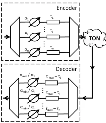
The principle of operation of the considered all-optical cryptography technique may be promptly
encoder where it is divided into n spectral slices. First, each of these slices receives an attenuation αi
(i= 1 to n); this corresponds to SAE. Then, in a second stage of encryption these slices are also
submitted to a delay τi. In frequency domain, the envelope of the signal corresponding to the i-th
spectral slice may be written as
H
e S
E j i
i i e i
, (1)where S
s
tejtdt is the Fourier transform of s(t), and He,i(ω) is the transfer function of theoptical band-pass filter (OBPF) that generates the the i-th spectral slice.
At the encoder output, an optical coupler or some other similar device is used to merge all slices into a
single encoded signal that is a distorted version of the input one. The encoded signal is, then,
expressed by
n i j i i e n i i i e H S E E 1 , 1 (2)and could be safely transmitted through a TON because, in case it is split and forwarded to an
unauthorized route, it should be, at least in principle, unintelligible for any malicious receiver.
Designating the minimum value of coefficient αi by αmin (maximum loss) and the maximum value
of τi by τmax, the authorized receiver may recover the transmitted signal by using a decoder which is
physically identical to the encoder but that applies attenuations αmin/αi and delays τmax- τi to each
spectral slice. Therefore, the decoded signal becomes
n i j i i d i e H E D 1 min , max / (3)with Hd,i(ω) standing for the transfer function of the OBPF used to recover the the i-th spectral slice.
As in any other optical signal processing technique, the analyzed encoding/ decoding scheme can
induce some deterioration to the input signal. In practice, such degradation could arise from
distortions imposed by the OBPFs and by interference between signals processed by adjacent spectral
slices. To evaluate the influence of such distortions, it is assumed that the input signal is noiseless and
it is recalled that its power is its mean square value, <s2(t)>, where <x(t)> denotes the average of x(t). It is also noted that the distortions generated by the encoding/ decoding processes cause a difference
between the decoded and input signals, nd(t)= d(t)- s(t) whose power is given by
nd
t
d
t s t
d
t d
t s t s
t2 2 2 2
2
(4)where d
t 12
Dejtd is the inverse Fourier transform of D() and carries the distortions caused by the OBPFs that generate the decoder (Eq. (3)) and encoder (Eqs. (3) and (2)) optical slices.Although, signal distortions are deterministic (Eqs. (3) and (2)), s(t) is random; hence, nd(t)may be
treated as a noise created when the input signal s(t) passes by the encoder and by the decoder.
Therefore, the optical signal-to-noise ratio, OSNR, caused by such devices is
d
t d
t
s t s
t t s t n t s OSNR d 2 2 2 2 2 2 , (5)
If the ideal condition d(t)= s(t) is achieved, then the denominator of (5) vanishes and OSNR tends to
infinity; this is in agreement with the assumption of noiseless input signal. Lower values of OSNR are
associated with higher signal degradations. Since d(t) depends on s(t) (see (3)), the average <s(t)d(t)>
in (5) may not be considered as the product of the individual averages <d(t)> and <s(t)>.
In this work, we assume that all OBPFs are described by an ideal unitary and rectangular profile in
such a way that
i ci i e i d B f rect H H 2 2 , , (6)where fci and Bi are, respectively, the center frequency and bandwidth of the i-th spectral slice. It is
also considered that Bi are contiguously distributed through the essential bandwidth Be of s(t); i.e.,
there is no superposition and no empty frequency range between any two adjacent spectral slices.
With these assumptions and substituting (2) and (6) in (3), it is easy to obtain
e S
D j max
min
(7)
or, in the time domain,
t mins
tmax
d (8)
This clearly shows that the decoded signal is a delayed and attenuated version of the input optical
signal. The cryptographic keys for coding and decoding signals encompass n, fci, Bi,αi, and τi (i= 1 to
n).
At this point it is important to stress some differences between the technique described above and
application in OCDMA systems. Nevertheless, in the latter approach non-coherent sources with
linewidths exceeding 15 nm are frequently considered [18]. This is not the case in the present work,
where we assume that signals externally modulate a laser source with relatively low linewidth, for
instance, 90 kHz. Therefore, here we deal with signals whose optical bandwidth has the same order of
magnitude of its bit rate. Such quantitative change is possible because technology improvements led
to the commercial availability of OBPFs with bandwidths as low as 3 GHz. On the one hand, in our
approach we need to deal with a relatively small number of slices. For example, a 40-GHz bandwidth
signal could be divided in at most eight 5-GHz slices. On the other hand, the strategy considered here
allows us to encrypt WDM-compatible signals without affecting their bandwidth and channel spacing
constraints. Also, since in our approach SAE is not used to provide access to multiple users, as is the
case for OCDMA technology, we have no restrictions concerning code orthogonality.
It should also be noted that used delays, τi, are on the order of the symbol periods of the input
signals. Since they are constant in the whole range of frequencies of the spectral slice, each spectral
component of the slice acquires its own phase shift. This is an important difference relative to the SPE
techniques used in [13], where a constant phase-shift is experienced by all frequency components of a
given spectral slice.
Another important issue for this work is the impact of the analyzed technique on the quality of the
encoded and decoded signals. The bit error rate (BER) is a good metric for both of them, if the
eavesdropper detects the encoded signals with digital receivers. The BER after the decoder, BERD,
should be as low as possible and typically accepted values are lower than 10-12 when no forward error correction (FEC) is used. On the other hand, the BER at the encoder output, BERE, should be as high
as possible to prevent signal interpretation by unauthorized receivers. We observe that for binary
information the maximum BER value is 50%; this corresponds to the case where a receiver randomly
chooses between 0- and 1- bits.
Although FEC is crucial to allow the transmission of high bit rates optical signals through long
distances, it should be carefully used when optical cryptography is considered. This happens because,
in principle, FEC could correct bit errors introduced by signals encoders and, thus, favor intruder
attacks. Therefore, there is a tradeoff between security and maximum propagation distance in systems
with physical-layer encryption. In this work, we assume that a signal is properly encoded when BERE
is ≥ 10% and consider that utilized FECs are not able to correct BERs higher than 10-3
.
III. SIMULATION SETUP
All simulations considered in this work were performed in a commercially available software
program. Since no assumption concerning S(ω) is made, (1)- (8) should work properly for any
modulation format and any bit rate. To illustrate the first of these properties, we consider simulations
regarding NRZ-OOK and DQPSK signals. As it is interesting to compare the performance of both of
This led to the choice for Rb= 40 Gbps because, at this bit rate, DQPSK is a modulation standard and
the electronics for implementing NRZ-OOK is not so complex. Obviously, the technique should work
for other higher and lower bit rates, provided that OBPFs with appropriate bandwidth and spectral
profiles are available. It should be noted that the optical spectrum of the considered 40 Gbps
NRZ-OOK and DQPSK signals occupy bandwidths of, respectively, 80 and 40 GHz. Therefore, they fit,
respectively, to the 100- and 50-GHz ITU grids. Such diversity is interesting to show that the
technique investigated in this paper applies for both of such grids.
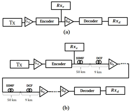
Fig. 2. Setups for (a) back-to-back and (b) propagation simulations.
Simulations concerning back-to-back and propagation of the encoded signal were considered. The
setup utilized for the back-to-back case is illustrated in Fig. 2(a). In a transmitter, Tx, a 2048
pseudo-random bit sequence (PRBS) is used to modulate an optical carrier at frequency fc= 193.1 THz with
either NRZ-OOK or DQPSK modulation schemes. The peak power of this optical signal is set to 0
dBm. A first optical amplifier boosts this signal that is then driven to the all-optical encoder. The
encoder acts accordingly to the description of Section II. At the output of such device, the signal
power is kept at 0 dBm thanks to gain Ge provided by the first optical amplifier. The BER
performance of this encoded signal is statistically evaluated after it is passed by a receiver, Rxe. Direct
and coherent detection are, respectively, assumed for NRZ-OOK and DQPSK signals. A second
amplifier boosts the encoded signal by a gain Gd. A decoder, as the one presented in Fig. 1, is utilized
to decode the optical signal which is finally detected by receiver Rxd. Gain Gd is also set to provide an
optical power of 0 dBm at the input of Rxd.
To simulate TON propagation, the encoded signal is also transmitted through a set of 10 50-km
dispersion is balanced out by 7.1km long dispersion compensating fibers (DCF) with dispersion of
-90 ps/(km.nm) at 193.1 THz. SSMF and DCF attenuations are, respectively, of 0.20 and 0.60 dB/km
and fiber losses are evened out by optical amplifiers of gain Gx placed at the end of each optical link.
In this way the peak power of the encoded signal remains at 0 dBm at the output of every optical link.
The noise figure of all optical amplifiers used in these simulations is of 5.0 dB. The optical
signal-to-noise ratio (OSNR) at the fiber input is 45 dB.
As in the back-to-back situation, at the receiver side, another optical amplifier, with gain Gd, boosts
the encoded signal in such a way that the peak power at the output of the decoder is also set to 0 dBm.
The encoded signal is then passed through the all-optical decoder where it is decrypted and then
photo-detected. The decoder OBPFs features are the same as those of the encoder. Once the optical
power at the input of the photo-detectors is always the same, we are able to make a fair comparison
between the bit error rates of the encoded and decoded signals.
IV. RESULTS AND DISCUSSIONS
In this section, we present the results concerning the performance of the considered technique.
Initially, to investigate the influence of slice attenuation and delay on BERE and BERD and to deal
with a tractable number of parameters, only three spectral slices are considered (subsections A, B, and
C). After some insights are provided by such initial analysis, the robustness of the technique against
some possible attacks (subsections D and E) and its propagation performance (subsection F) are
evaluated by considering seven spectral slices.
A. NRZ-OOK Signals: Spectral and Time Domain Analysis
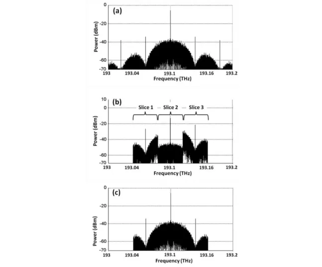
Fig. 3 illustrates the optical spectra of an input NRZ-OOK signal at the (a) encoder input, (b)
encoder output, and (c) decoder output for the back-to-back case (no TON between the encoder and
decoder) with n= 3, α1= 5 dB, α2= 20 dB, and α3= 0 dB e τ1= τ2= τ3= 0 ps. Fig. 3(b) evidences the
presence of three spectral slices 40 GHz. Abrupt spectral changes in the interface between spectral
slices are a consequence of the considered rectangular filter profiles; such filters are also responsible
for the suppression of spectral components outside the range between 193.04 and 193.16 THz (fc-
3Rb/2 and fc- 3Rb/2). This suppression is also observed for the decoded signal spectrum shown in Fig.
3(c). However, since the amplitude of the suppressed spectral components is relatively low, its
influence on the decoded signal is small; in fact, our simulation results indicate that BERD is lower
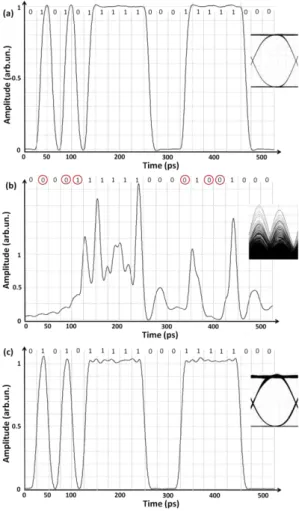
It is also important to investigate the technique in time-domain. For this sake, Fig. 4 illustrates a
21-bit sequence extracted from the considered 2048 PRBS for the signals at the (a) encoder input, (b)
encoder output, and (c) decoder output for the back-to-back case; eye-diagrams, for the 2048 PRBS,
are shown as an inset and attenuation and delay parameters are the same as before. Fig. 4(b) shows
that the encoded signal is a distorted version of the input one; in fact, such encoded signal resembles
an analog one and its eye-diagram is completely closed. It should be noted that eventually a space in
the input signal appears as a signal with relatively high power in the encoded signal; also, a mark in
the input signal occasionally is observed as a low power signal in its encoded version. This is a
consequence of pulse spreading that is theoretically expected, as suggested by the inverse Fourier
Transform of (2)
ni
i i e ih t
t s t e
1
,
(9)where he,i(t) is the inverse Fourier Transform of He,i(ω) and '*' represents the convolution operation
between two signals x
t and y
t ,x
t yt
x
t yt d. In fact, since 1 and 2 are differentfrom unity, the aforementioned pulse spreading presented in Fig. 4(b) is a result of a destructive Fig. 3. Optical spectra of an input NRZ-OOK signal at the (a) encoder input, (b) encoder output, and (c) decoder output
interference among the ihe,i(t) terms in the summation of (9). A good theoretical background for this
discussion is found at [19].
As indicated by the bit sequence on the top of Figs. 4(a) and (b), if the encoded sequence were
detected six out of 21 bits would be in error (29% of errors). This is in rather good agreement with
BERE= 33.6% estimated by our simulation software for the 2048 PRBS. Fig. 4(c) suggests that the
decoded signal is very similar to the input one. A small ripple is a consequence of the previously
discussed suppression of some spectral components. In fact, for the results of Fig. 4, <s2(t)>= 1.8912, <d2(t)>= 1.8897, and <s(t)d(t)>= 1.8890 (all in arbitrary units); this leads to an OSNR of ~ 28 dB. Such high value agrees with the fact that the decoded signal is considerably similar to the input one.
B. NRZ-OOK Signals: Influence of Spectral Slices Attenuation and Delay on the Bit Error Rate of Encoded and Decoded Signals.
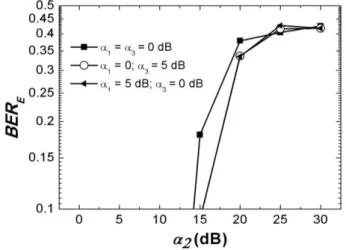
Considering n= 3, Fig. 5 illustrates the BER of the encoded signal as a function of α2 and for i) α1=
α3 = 0 dB; ii) α1= 0 dB and α3= 5 dB, and iii) α1= 5 dB and α3= 0 dB. As α2 is increased, BERE also
increases. Moreover, for α2> 20 dB, BERE acquires an asymptotical behavior with a maximum value
of ~45%. This is in quite good agreement with the maximum BER value of 50% pointed out in
Section II. It is observed that the curves corresponding to cases ii) and iii) are closely superimposed; Fig. 4. An NRZ-OOK sequence for the signals at the (a) encoder input, (b) encoder output, and (c) decoder output for
this happens because of the symmetry between the spectral slices with i= 1 and i= 3. In all of these
cases the BER of the decoded signals were below 10-15, which suggest an appropriate recovering of the input signal.
Figure 6 exhibits the influence of delays applied to the BER of the encoded signal when 1= 2=
3= 0 dB. As before, the n= 3 spectral slicing situation is considered. The i-th spectral slice delay is
varied in increments of bit duration, Tb. Generally speaking, BERE increases when τi also increases.
Thanks to the spectral symmetry of the considered case, variations on τ1 and τ3 are equivalent in terms
of their impact on BERE. Moreover, since the amplitude of the central spectral slice (i= 2) is higher
than those of the other two ones, BERE is mostly affected by variations on τ2. However, even for τ2
variations, BERE is at most of ~0.2%, which is well below our considered limit of 10%. This suggests
that delays exert a relatively lower influence on BERE and that they should not be used as a single
cryptographic key parameter to provide good quality (high BER) to encoded signals. The BER of the
decoded signal for all the cases considered in Fig. 6 was, again, inferior to 10-15 and indicates the good quality of the technique in back-to-back situations.
Fig. 6. Dependence between the BER of an encoded NRZ-OOK signal and spectral slice delays. Other encoding parameters are n= 3 and 1= 2= 3= 0 dB.
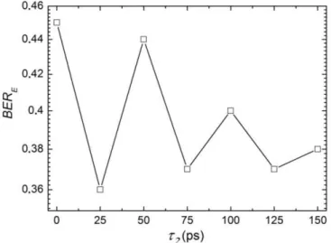
We also consider the case where delays are applied in combination to attenuations to the spectral
slices. For n= 3, Fig. 7 shows that BERE~ 0.01% for τ2= 0, but that it becomes higher than 20% for
some values of τ2. In contrast to the results presented in Fig. 6, this indicates that delays do impose a
meaningful increment to BERE when they are applied in conjunction to attenuations to the spectral
slices of the encoded signal. Fig. 7 also shows there is no simple trend between BERE and τ2. At first
sight, this may not seem an attractive point because it may require a very good matching between the
delays utilized in the encoder and in the decoder. However, the absence of tendency between both of
these variables also improves the security of the cryptographic key and could be used as an
advantageous issue. Results discussed in this paragraph illustrate the effectiveness of simultaneously
attenuating and delaying spectral slices for signal encryption purposes.
C. DQPSK Signals
To illustrate the effect of the technique on multi-level phase-modulated signals, we plot on Fig. 8
the optical spectra of 40 Gbps DQPSK signals at the (a) encoder input, (b) encoder output, and (c)
decoder output for the back-to-back cases. All parameters are the same utilized to obtain the results
presented in Fig. 3 with exception of the optical band-pass filters utilized to generate the optical slices
whose bandwidths are now of 20 GHz. This is necessary because DQPSK signals convey the double
of bits per symbol than NRZ-OOK ones and so their bandwidth are halved. In accordance to this, Fig.
8(a) illustrates that the discrete spectral components are spaced from the carrier one by integer
multiples of 20 GHz. As in the case of NRZ-OOK signals, the distortion of the encoded signal and the
spectral suppression of spectral components outside the range of the considered slices are also verified
in Figs. 8(b) and 8(c).
In the time domain, the in-phase and quadrature-phase components of the input, encoded and
decoded DQPSK signals also present the same characteristics as those shown in Fig. 4 for the
NRZ-OOK signals. For this only reason, results concerning such temporal analysis are not shown here. The
BER of the decoded signal is again lower than 10-15. Moreover, results indicate that <s2(t)>= 1.2164, <d 2(t)>= 1.2183 <s(t)d(t)>= 1.2169 (all in arbitrary units); hence, OSNR is ~31 dB that, again, agrees with the fact that the decoded signal is very similar to the input one.
Fig. 9(a) presents the trend between BERE and α2 for n= 3. As for the NRZ-OOK case, whose
curves are reproduced in Fig. 9(b), BERE grows monotonically when α2 is augmented. However, the
maximum value of BERE is now around 28% and happens when one of the side slices (i= 1 or i= 3) is
also attenuated. The higher BERE maximum value for NRZ-OOK signals, ~45%, is a consequence
that amplitude-modulated signals are more affected by attenuation distortions (caused by SAE) than
phase-modulated signals.
The relation between BERE and τi for n= 3 is depicted in Fig. 10(a). Differently from the NRZ case,
BERE often assumes values higher than 10%. In addition to such difference, increasing τi may either
cause BERE to rise or to drop, which has the pros and cons previously discussed. Both of these
dissimilarities with the NRZ situation are possibly explained by recalling the fact that time delays Fig. 8. Optical spectra of an input DQPSK signal at the (a) encoder input, (b) encoder output, and (c) decoder output
impose signal phase changes. Therefore, the influence of such delays on phase-shifted signals is
expected to be much more effective than in amplitude-shifted ones. To facilitate a comparison
between the DQPSK and NRZ-OOK situations, Fig. 9(b) reproduces the curves plotted in Fig. 5.
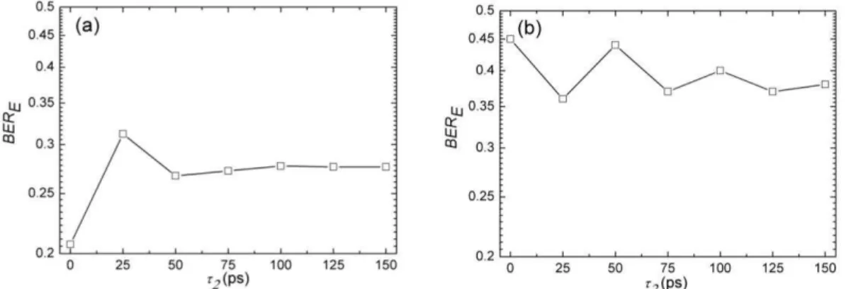
The graph of Fig. 11(a) shows the performance of BERE when a delay in the central slice (i= 2) is
applied in combination to attenuations to the spectral slices (n= 3, 1= 5, dB 2= 20 dB, 3= 0 dB,
and τ1= τ3= 0 ps). From τ2= 0 to 25 ps, BERE is increased from ~20% to ~32%. At higher values of τ2,
BERE tends to an asymptotical value of ~28%. As indicated in Fig. 11(b), which is a reproduction of
Fig. 7, such tendency also happens, for higher values of τ2, in the NRZ-OOK situation. Physically, this
asymptotical behavior means that, after a given critical delay value, τc, signal becomes so distorted
that the bit error rate of the encoded signal cannot be further enhanced. The critical delay is shorter for
DQPSK signals, because, as stated before, phase-shifted signals are more affected by delay variations
than amplitude-shifted ones. In despite of this asymptotical convergence for BERE, it is shown in
subsection IV.F that there are important benefits in utilizing high values of τi.
Fig. 10. Dependences between the BER of (a) an encoded DQPSK signal and (b) an encoded NRZ-OOK signal and spectral slice delays. Other encoding parameters are n= 3 and 1= 2= 3= 0 dB. (b)
D. Propagation
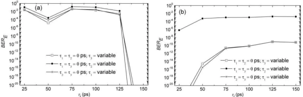
It is important to evaluate the performance of signals after propagation through a TON. Fig. 12
shows the BERD performance of NRZ-OOK signals when the propagation scenario described in
Section III (Fig. 2b) is taken into account for five different optical powers and for Be= a) 60 GHz and
b) 120 GHz. Encoding parameters are n= 7, 1= 8 dB, 2= 6 dB, 3= 0 dB, 4= 1 dB, 5= 1 dB, 6=
5 dB, and 7= 10 dB, τ1= 3Tb, τ2= 7Tb, τ3= 8Tb, τ4= 10Tb, τ5= 8Tb, τ6= 6Tb, and τ7= 7Tb. It is considered
that polarization mode dispersion (PMD) is compensated by digital signal processing (DSP) elements
at the receiver side. In fact, such compensation is necessary even if uncoded signals are propagated.
For the 60 GHz case, distances of up to 400 km are possible (BERD 10 -12
) for -3 and -6 dBm. Higher
powers lead to signal degradation possibly associated to self-phase modulation (SPM). For Be= 120
GHz, the maximum reach is around 350 km and happens when -3 and 0 dBm are used.
A similar analysis is performed for DQPSK signals with the following encoding parameters n= 7,
1= 8 dB, 2= 6 dB, 3= 0 dB, 4= 1 dB, 5= 1 dB, 6= 5 dB, and 7= 10 dB, τ1= 3Ts, τ2= 7Ts, τ3=
8Ts, τ4= 10Ts, τ5= 8Ts, τ6= 6Ts, and τ7= 7Ts, where Ts is the symbol period. Results are shown in Fig. 13
where it is observed that the higher the optical power is, the higher BERD becomes. This is again a
manifestation of SPM degradation. Assuming a FEC able to correct BERs lower than 10-3 is used, it is Fig. 12. BER of the decoded NRZ-OOK signals with effective bandwidth of (a) 60 and (b) 120 GHz as a function of
propagation distance for different optical powers.
easy to verify that signals with Be= 30 and 60 GHz lead, respectively, to propagation distances of 400
and 300 km for optical powers of -3 and -6 dBm. It is interesting to note that for both modulation
formats, the use of a lower Be caused a better propagation distance performance. Also, in all the
considered cases, propagation distances are compatible with those expected for metropolitan area
networks.
It should be noted that in practice the shape of the filters will not be ideal as considered in (4).
Therefore, (6) will no longer be valid and some pulse distortion is expected for the decoded signal.
This could be solved by optimizing the OBPF frequency spacing [20] or by using decoder filters with
the reciprocal profile of those utilized in the encoder, i.e. He,i(ω)= 1/Hd,i(ω) in the spectral range of
interest.
E. Robustness to Input Bit Patterns
As a signal is propagated through a TON, it may be intercepted by an intruder who attempts to
decode it. Two techniques for achieving such goal are approached in this subsection and in the next
one. Here, the resilience of the technique to input bit patterns (IBP) is considered. Subsection F
discusses the technique robustness to brute force attacks.
Fig. 14 illustrates an encoded signal when the following IBPs are repeated five times and utilized to
modulate an NRZ-OOK input signal: a) 10, b) 110, c) 1110, and d) 11110; n= 7, attenuations 1= 8
dB, 2= 6 dB, 3= 0 dB, 4= 1 dB, 5= 1 dB, 6= 5 dB, and 7= 10 dB and τi= 0 (i= 1 to 7) were
utilized. To investigate the performance of the cryptographic technique for different bandwidths, we
consider the cases where the effective bandwidths of the signals are Be= 3Rb= 120 GHz and Be=
3Rb/2= 60 GHz. In both of them, an output bit pattern (OBP) is always observed. In fact, even when a
PRBS is used it is possible to find some kind of output pattern; i.e. the encoded signal that
corresponds to, for example, the input bit sequence 111 is approximately the same no matter the
position of such sequence in the PRBS. An intruder could use this fact to promote an attack and try to
discover the encoding cryptographic key. After sending a given input bit pattern, such malicious user
could utilize a scope to save the encoded signal waveform and to perform off-line calculations to
determine the set of considered attenuations.
OBP is broken when delays are included in the cryptographic key. Figs. 15 (a), (b), and (c) show
this important feature for the same parameters considered in the results presented in Fig. 12, but with
τ1= 3Tb, τ2= 7Tb, τ3= 8Tb, τ4= 10Tb, τ5= 8Tb, τ6= 6Tb, and τ7= 7Tb. The maximum value of τi is, thus,
τmax= 10Tb. The absence of an OBP is a consequence of temporal scrambling caused by such delays,
which, indeed corresponds to an artificially introduced dispersion. It is interesting to note that, unlike
in fiber and other practical optical materials, this dispersion does not vary monotonically with
frequency because each spectral slice receives its own delay.
Fig. 14. Input NRZ-OOK signals for bit patterns a) 10, b) 110, c) 1110, and d) 11110 repeated five times and their correspondent output signals with effective bandwidths of 60 and 120 GHz. Encoding parameters are: n= 7, 1= 8 dB,
However, if the IBP is repeated during time intervals longer than the maximum value of τi, then the
OBP reappears. This is shown in Fig. 15(d), after the second repetition of the 5-bits input sequence
11110. Hence τmax could be evaluated after an attack with a properly long IBP sequence.
It is important to note that, in practice, this kind of attack could be avoided. For example, most of
TON client equipment utilizes time division multiplexing (TDM) technology to send its user data.
Therefore, if the eavesdropper is one of these users, his data is interleaved with those of other users
and he cannot send a very long IBP. In this case, τmax should be set to be larger than the duration of the
longest sequence allowed for a user. If, on the other hand, a TON client transmits its user data in
frames that do not use TDM, a different cryptographic key could be utilized for each frame. In this Fig. 15. Input NRZ-OOK signals for bit patterns a) 10, b) 110, c) 1110, and d) 11110 repeated five times and their correspondent output signals with effective bandwidths of 60 and 120 GHz. Encoding parameters are: n= 7, 1= 8 dB,
2= 6 dB, 3= 0 dB, 4= 1 dB, 5= 1 dB, 6= 5 dB, and 7= 10 dB, τ1= 3Tb, τ2= 7Tb, τ3= 8Tb, τ4= 10Tb, τ5= 8Tb, τ6=
way, the eavesdropper could discover the value of τmax used to encrypt his own data, but not of other
users.
Figs. 16 and 17 show the influence of IBP for an input DQPSK signal, respectively, with and
without the application of delays to the spectral slices. Attenuations are 1= 8 dB, 2= 6 dB, 3= 0
dB, 4= 1 dB, 5= 1 dB, 6= 5 dB, and 7= 10 dB and, only for Fig. 17, delays are τ1= 3Ts, τ2= 7Ts,
τ3= 8Ts, τ4= 10Ts, τ5= 8Ts, τ6= 6Ts, and τ7= 7Ts, where Ts is the symbol period. The considered
bandwidths are Be= 60 and 30 GHz. Behaviors and conclusions are the same as in the case for
NRZ-OOK input signals. It is interesting to note that we performed simulations concerning the technique
reported in [13] and found that, as in the case of SAE analyzed here, SPE also leads to OBP.
Fig. 16. Input DQPSK signals for bit patterns a) 10, b) 110, c) 1110, and d) 11110 repeated five times and their correspondent output signals with effective bandwidths of 30 and 60 GHz. Encoding parameters are: n= 7, 1= 8 dB,
BERE is a good metric for evaluating the quality of the encoded signal when digital receivers are
used by unauthorized users. However, the discussion presented in this subsection shows that under
waveform attacks, such metric is not enough to describe the capacity of eavesdroppers decoding
signals. In this case, the degree of signal scrambling should also be taken into account.
F. Robustness to Brute Force Attacks
In brute force attacks, the eavesdropper systematically varies the parameters of the cryptographic
key in order to decode the encrypted signal. Here, we consider an example of such attack by
supposing that the eavesdropper knows the position, the bandwidth and the attenuations of the
cryptographic key. Therefore, he should discover only the values of τi. Encoding parameters are the
Fig. 17. Input DQPSK signals for bit patterns a) 10, b) 110, c) 1110, and d) 11110 repeated five times and their correspondent output signals with effective bandwidths of 30 and 60 GHz. Encoding parameters are: n= 7, 1= 8 dB,
2= 6 dB, 3= 0 dB, 4= 1 dB, 5= 1 dB, 6= 5 dB, and 7= 10 dB, τ1= 3Ts, τ2= 7Ts, τ3= 8Ts, τ4= 10Ts, τ5= 8Ts, τ6= 6Ts,
same as those for the results presented in Fig. 15. Only the NRZ-OOK case is considered in this
subsection and it is assumed that the attack is well succeeded if BERD 10 -12
for a FEC-less situation.
Table I illustrates the values of BERD for some combinations of τi. It is seen that the attack becomes
successful when, at least, the delays of the three central spectral slices (τ3, τ4 and τ5) are precisely
known.
TABLE I.BER OF THE DECODED SIGNAL FOR SEVERAL COMBINATIONS OF ΤI DURING A POSSIBLE BRUTE FORCE ATTACK.
Combination BERd
τ1= τ2= τ3= τ4= τ5= τ6= τ7= 0; 36%
τ1= τ2= τ3= τ5= τ6= τ7= 0; τ4 correct 36%
τ1= τ2= τ5= τ6= τ7= 0; τ3 and τ4 correct 13%
τ1= τ2= τ6= τ7= 0; τ3, τ4 and τ5 correct 2.7 10
-13
τ1= τ6= τ7= 0; τ2, τ3, τ4 and τ5 correct 2.7 10
-13
τ1= τ7= 0; τ2, τ3, τ4, τ5 and τ6 correct < 1.0 10-15
In principle, τi is a continuous random variable. However, if the delay used by the eavesdropper, τi'
(i= 1 to n), is in the range τi- Δτi τi' τi+ Δτi and Δτi is small enough, the attack may still be
prosperous. Computationally, it is hard to determine a minimum value for Δτi because this requires the
use of very high sample rates, fS. In fact our simulations have shown that reliable results demand the
product (fSΔτi) to be higher than 40 (i.e., there must be at least 40 sampling points in the interval Δτi).
Within our presently available computational power, we found that Δτi= 1 ps leads to BERd~ 3%. We
will consider this Δτi,max= 1 ps limit as a very conservative estimate for Δτi.
Assuming that τmax= 10Tb= 250 ps is, in a pessimistic scenario for security, known and considering
Δτi,max= 1 ps shows that the brute force attack may require 250 tries per spectral slice to be effective.
Since Table I shows that τi' must be properly known for at least three spectral slices, then the
unauthorized user may need up to 250!/(247!)~ 1.5 107 attempts to perform a successful attack. This is also a very conservative estimate because, in practice, the encoded signal would be possibly
captured inside the TON and would then be propagated to the unauthorized receiver facilities. For this
reason, noise and other physical impairments accumulated through the propagation would corrupt the
encoded signal whose quality would be worse than that considered in Table I (back-to-back case). To
compensate these deleterious effects, the eavesdropper could either work with a shorter Δτi, or deal
with a higher number of spectral slices. In both of these situations, the number of attempts necessary
for achieving a prosperous attack would increase. Fig. 18 shows the number of necessary brute force
attacks, for τmax= 10Tb and Rb= 40 Gbps, as a function Δτi and the number of considered slices, ns,
necessary to decode the optical signal. It is seen that if ns needs to be increased by only one, the
number of necessary attempts to decode the signal raises by at least two orders of magnitude. A
decrease from 1 ps to 50 fs in Δτi also implies an increase of two orders of magnitude in the number of
V. CONCLUSION
We have systematically analyzed the performance of a new two-stage all-optical cryptography
technique that is bit-rate independent and transparent to modulation formats. It was shown that the
first of these stages, related to spectral amplitude encoding, is essential to increase the BER of
encoded signals to desired elevated levels. In fact, our results show that BERE as high as 45 and 28%
are attainable, respectively, for input NRZ-OOK and DQPSK signals. The second stage performs
spectral delay encoding and its use is mandatory to promote temporal signal scrambling and to
increase the degree of security against attacks based on waveform analysis. At the receiver side, our
results indicate that the considered signals may be properly decoded after propagation distances
comparable to those expected for metropolitan area networks. These results suggest that the technique
may have a very good practical performance and serve as a good foundation for future experimental
research.
Since the investigated technique relies solely on linear devices and effects, its implementation is
much simpler and advantageous in relation to other presented in literature [14- 16]. Moreover, the use
of spectral delay encoding also avoids, to certain extent, the presence of OBP that happens in [13] and
constitute another upside for the technique considered here.
Although our analysis was not focused on any particular technology, the approached technique
could be implemented either with discrete components or in integrated optics. In the first of these
approaches, the encoder and decoder could be implemented by properly connecting specially designed
optical multiplexers, optical attenuators, and optical delay lines. Alternatively, a basic 4-f setup [18]
whose amplitude and delays are controlled by a spatial light modulator (SLM) could be utilized as
0.0 0.2 0.4 0.6 0.8 1.0
1x10⁶ 1x10⁸ 1x10¹⁰ 1x10¹² 1x10¹⁴ 1x10¹⁶ 1x10¹⁸ 1x10²⁰ 1x10²² 1x1024 1x1026 1x1028
3
4
5
6
7
n
s=
N u m b e r o f A tt e m p tsi (ps)
well. Silicon photonics is suitable for deploying the considered devices in an integrated optics
strategy. In all of these cases, special attention should be given to the influence of temperature over
the frequency position of OBPFs and other optical devices.
Finally, we remark that the technique could also be extended to a dynamic approach, where the
cryptographic key varies with time. In this situation, the encoder/ decoder attenuators could be
substituted by optical modulators. As is the case for most of encrypting technologies dynamic keys
are of interest because they increase the degree of communications security.
ACKNOWLEDGMENT
Authors thank CNPq and FAPESP for funding this work in the scope of Fotonicom Program, under
grants 574017/2008-9, 08/57857-2, 310644/2011-9, and 310990/2011-4. Authors also thank Prof.
Hugo L. Fragnito and Prof. Ben-Hur V. Borges for valuable discussions. Finally, authors thank
VPIphotonicsTM for providing academic licenses of the simulation software utilized in this work.
REFERENCES
[1] K. Kitayama, M. Sasaki, S. Araki, M. Tsubokawa, A. Tomita, K. Inoue, K. Harasawa, Y. Nagasako, and A. Takada, "Security in Photonic Networks: Threats and Security Enhancement," IEEE/OSA Journal of Lightwave Technology, vol. 29, pp. 3210-3222, November, 2011.
[2] K. Shaneman, and S. Gray, "Optical network security: technical analysis of fiber tapping mechanisms and methods for detection & prevention," IEEE Military Communications Conference, vol. 2, pp. 711-716, 2004.
[3] N. Skorin-Kapov, J. Chen, and L. Wosinska, "A New Approach to Optical Networks Security: Attack-Aware Routing and Wavelength Assignment," IEEE/ACM Transactions on Networking, vol. 18, pp. 750-760, June 2010.
[4] L. Zhang, X. Xin, B. Liu, and Y. Wang, "Secure OFDM-PON Based on Chaos Scrambling," IEEE Photonics Technology Letters, vol. 23, pp. 998-1000, July 2011.
[5] P. Juleang, R. Putthacharoen, S. Mitatha, and P.P. Yupapin, “Highly secured optical communication by optical key and identification
address,” Elsevier Optik - International Journal for Light and Electron Optics, vol. 124, pp. 834-839, May 2013.
[6] A. Argyris, D. Syvridis, L. Larger, V. Annovazzi-Lodi, P. Colet, I. Fischer, J. García-Ojalvo, C.R. Mirasso, L. Pesquera, and K.A. Shore, "Chaos-based communications at high bit rates using commercial fibre-optic links," Nature 438, pp. 343-346, 2005.
[7] Y. Hong, M.W. Lee, J. Paul, P.S. Spencer, and K.A. Shore, “GHz Bandwidth Message Transmission Using Chaotic Vertical-Cavity Surface-Emitting Lasers,” IEEE/OSAJournal of Lightwave Technology, vol. 27, pp. 5099-5105, november 2009.
[8] J-P. Goedgebuer, P. Levy, L. Larger, C-C. Chen, and W.T. Rhodes, "Optical communication with synchronized hyperchaos generated electrooptically," IEEE Journal of Quantum Electronics, vol. 38, pp. 1178-1183, September 2002.
[9] N. Kostinski, K. Kravtsov, and P.R. Prucnal, "Demonstration of an All-Optical OCDMA Encryption and Decryption System With Variable Two-Code Keying," IEEE Photonics Technology Letters, vol. 20, pp. 2045-2047, December 2008.
[10] T.H. Shake, "Security performance of optical CDMA Against eavesdropping," IEEE/OSAJournal of Lightwave Technology, vol. 23, pp. 655-670, February 2005.
[11] C-C. Yang, “Hybrid Wavelength-Division-Multiplexing/Spectral-Amplitude-Coding Optical CDMA System,” IEEE Photonics
Technology Letters, vol. 17, pp. 1343-1345, june 2005.
[12] K. Kitayama, X. Wang, and N. Wada, “OCDMA Over WDM PON—Solution Path to Gigabit-Symmetric FTTH,” IEEE/OSAJournal
of Lightwave Technology, vol. 24, pp. 1654-1662, 2006.
[13] J.A. Cornejo, C.E. Perez, and J-L. B. Tocnaye, “Non-invasive WDM channel scrambling for secure high data rate optical
transmissions,” IEEE/OSA Journal of Lightwave Technology, vol. 25, pp. 2081-2089, 2007.
[14] L. Yi, T. Zhang, Z. Li, J. Zhou, Y. Dong, W. Hu, “Secure optical communication using stimulated Brillouin scattering in optical fiber,”
Elsevier Optics Communications, vol. 290, pp. 146-151, March 2013.
[15] S. Singh, Lovkesh, X. Ye, and R.S. Kaler, “Design of Ultrafast Encryption and Decryption Circuits for Secured Optical Networks,”
IEEE Journal of Quantum Electronics, vol. 48, pp. 1547-1553, 2012.
[16] K. Mukherjee, “A method of implementation of frequency encoded all optical encryption decryption using four wave mixing,”
Elsevier Optik - International Journal for Light and Electron Optics, vol. 122, pp. 1407-1411, 2011.
[17] M.L.F. Abbade, L.A. Fossaluzza Jr., R.F. Silva, and E.A.M. Fagotto, “Criptografia Óptica Mediante Controle Analógico da Amplitude
e do Atraso de Fatias Espectrais: Análise para Sinais NRZ,” (in Portuguese) MOMAG ,2012.
[18] M. Kavehrad, Fellow, and D. Zaccarh, “Optical Code-Division-Multiplexed Systems Based on Spectral Encoding of Noncoherent
Sources,” Journal of Lightwave Technology, vol. 13, pp. 534-545, 1995. B.P. Lathi, "Modern Digital and Analog Communication
Systems," 3rd Edition, Oxford Press, 1998.
[19] B.P. Lathi, "Modern Digital and Analog Communication Systems," 3rd Edition, Oxford Press, 1998.
[20] R.F. Silva, "Análise de criptografia óptica realizada mediante controle da amplitude e do atraso de fatias espectrais geradas com perfil