Abstract— This work studies a Transcutaneous Energy Transmitter (TET) which uses electromagnetic fields to transfer power from outside the body to an artificial organ in the body, working like a high frequency transformer with the skin being part of the magnetic coupling between the primary (external coil) and secondary (internal coil). For this reason, this project made two different kinds of analyses of the efficiency and the induced current density in a biologic tissue: first, simulations were performed using core types of distinct geometries, each with multiples sizes, ranking which type is more recommended; second, the sensitivity of the chosen core type to misalignments was evaluated for different dimensions. In addition, the sensitivity to the core permeability was also investigated for both analyses.
Index Terms—Finite Element Method, Induced Current Density,
Transcutaneous Energy Transmitter.
I. INTRODUCTION
The advancement of medicine spawned many artificial organs that are mostly or completely
implanted inside the body. Such organs require the supply of power internally to the body, bringing
more complexity to the complete system and often forcing the patients to have wires crossing their
skin, what can cause infections and discomfort. Trying to reduce these complexities, several
researchers widely study options to transfer electric energy to an internal electrical subsystem of
direct current (DC) that provides power to these artificial organs and their internal backup battery
[1]-[3]. This technology, called Transcutaneous Energy Transmission, or TET, normally works through
inductive link similar to a transformer with the primary and secondary windings placed above and
below the skin, respectively [4].
However, the skin between the windings can vary in thickness more than 5 mm, creating low
coupling and considerable high induced currents, and thus requiring higher voltage from the external
power supply and working at low efficiency.
Therefore, a proper design of this system will allow obtaining a highly efficient system with fewer
losses that can be used in several different implanted artificial organs projects. During the designing
phase, the engineer deals with several important decisions with the core geometry and size being two
of them: “what is the best core geometry and size that would instigate the least discomfort to the
patient without losing reliability at unsteady situations?” This paper introduces analyses of different
A Systematic Sensitivity Analysis of the
Performance of a Transcutaneous Energy
Transmitter for Design Purposes
Daniela Wolter Ferreira, Luiz Lebensztajn,TET project parameters, showing how the performance of the TET is affected with the different sizes,
geometries and core permeability of the TET.
The paper is organized as follows: In Section II, the transcutaneous energy transmitter system is
briefly presented with the collateral effect that it may cause. In Sections III, the methodology is
described, pointing out the different simulated core types. Afterwards, the achieved results are
analyzed in Section IV, which is divided in the two steps of methodology: evaluation of the core type
with aligned coils; and evaluation of the sensitivity of the chosen core type to misalignments. Finally,
the conclusion is drawn in Section V.
II. TRANSCUTANEOUS ENERGY TRANSMITTER SYSTEM AND ITS EFFECTS ON BIOLOGICAL TISSUES
A. Transcutaneous Energy Transmitter
Most of the studied proposals of TET development are based on the principle of electromagnetic
field, transferring energy wirelessly from an external coil to a coil inside the body. It is similar to a
transformer with the primary coil outside the body transmitting power to a secondary coil inside the
body and having the skin and fat as part of the inductive link between the coils. Thus, the coils form a
weakly coupled transformer as they are not connected by a common core and they could be
misaligned during any small movement from the patient. For this reason, in this work, the primary and
secondary coils and their respective cores are considered a single element called transformer.
It was already presented in [5] that the coils should be distributing their turns across the radii
instead of concentrating them at the outer circumferences. Thus, in this paper, the external and
internal coils and cores constitute a planar transformer.
The medium between the transmitting and receiving systems contains the skin and could also
contain fat, of which the dielectric properties vary with the electromagnetic wave frequency as
collected by [6]. Since these tissues vary their thickness from person to person, the gap between the
transmitter and the receiver can vary from 5 to 30 mm, what characterize the TET as a transformer
with a large gap.
B. Electromagnetic Effects on Biological Tissues
Since the biological tissue in between the inductive link has a small conductivity, currents may be
induced due to the process of transmission. These currents can stimulate neural or muscle excitation
or actions as it has been researched for MRI (Magnetic Resonant Images) [7]. Thus, the restriction of
the induced current magnitude flowing through a surface of the biological tissue can minimize these
non-desired effects. This induced current density is expressed in Ampere per square meter (A/m2) as:
E
J
. (1)where E is the root mean square (RMS) electric field (V/m); and is the electrical conductivity of
the biological tissue (S/m).
There is intense discussion in this regard trying to establish limits for such effects. In Brazil, the
the International Commission on Non-Ionizing Radiation Protection (ICNIRP) [8]. According to
ICNIRP rules, a patient that knows the risk of the exposure to this magnetic field and is oriented to
follow the right procedure to minimize the risks can be exposed at a maximum value of the induced
RMS current density in mA/m2 not exceeding the value of the frequency divided by one hundred, i.e.,
⁄ .
Therefore, this paper works with the concept of relative current density in the skin in percentage,
which is the induced current density divided by the limit of it at the frequency of the induction and
multiplied by one hundred (J/Jmax.100%). Since the acceptable limit by ICNIRP is the frequency
divided by 100, the relative current density is the induced current in mA/m2 divided by the frequency
and multiplied by 10000.
III. METHODOLOGY
The main idea of this paper is to explore the TET projects ability to provide more comfort and
reliability to the patient. But how can someone measure comfort or stability? Someone could say that
discomfort is measured by anything that takes the patient out of his routine, like carrying a heavy
weight or big object. Regarding the stability, the TET is considered reliable if it functions at
comparable performance even in uncommon situations, such as an unusual position as when the
primary and the secondary coils are misaligned.
In this way, during the design phase of the TET, the engineer should seek to maximize efficiency
and/or minimize the volume or weight of the TET, taking in consideration the undesirable conditions
to which the TET could be subjected and the constraints of the project – relative induced current
density in the biological tissue and secondary output voltage within the required range.
Since part of the TET will be is positioned in the body of the patient, it will be subjected to different
kind of coupling situations, such as:
Distance between the coils – the skin thickness could vary according to the patient.
Distance between the axes of the coils – since the secondary coil is position inside the body, the
alignment between the coils is very hard to achieve.
The parameters of the TET (degrees of freedom) that could help to provide the requirements of this
project (maximum efficiency, minimum volume, low relative induced current density) could be:
Parameters related to the magnetic properties, such as number of turns as well as relative
permeability of the ferromagnetic material, internal and external diameters, and geometry of the
cores.
Parameters related to the electric system, such as applied voltage and frequency.
In this work, different simulations were performed using Finite Element Method (FEM) through
Flux software [9]. In Flux, the geometry considering magnetic cores (gray), copper coils (green), skin
external to the body, is involved by air while the secondary core, underneath the skin, is involved by
fat. The thickness of the simulated skin was considered to be 5 mm, thus the gap between primary and
secondary coils is 5 mm. The simulations considered the electrical and magnetic properties of the
skin, fat, copper coils and magnetic cores, as will be explained in the following pages.
Fig. 1. Geometry drawn in Flux.
First, the TET was implemented in Flux2D considering the five different geometries of core shown
in Fig. 2 plus coreless coils, i.e., the coils with no magnetic core around. The Flux2D software
performed a set of simulations with the coils aligned for the range of dimensions shown in Table I. All
the geometrical parameters are shown in Fig. 1.
TABLE I. DIMENSIONS WITH THEIR DEFAULT VALUES AND RANGE OF SIMULATION
Dimensions Default Range
Frequency 100 kHz [50 300] kHz Outer Core Diameter 50 mm [45 70] mm Inner Core Diameter 40 mm [20 45] mm Central Core Diameter 10 mm [8 24] mm Primary wire turns 23 turns [23 45] turns Secondary wire turns 45 turns [23 45] turns Relative Core Permeability 3400 [2 4000]
Fig. 2. Different geometries of the TET.
Note that all the analyzed geometries are circular with small differences. A circular core was used
due to the shape of the coil winding and because sharp corners could hurt the patient, what would
directly affect his comfort. Following this trend of thought, the more round the core geometry is, the
more comfortable the TET is for the patient. Furthermore, a square coil would add an instability
problem to the system in regards to misalignment. Considering that the central axes are lined up, a
round core is completely aligned at any rotational position of the cores. In addition, when the axes are
displaced, the TET behaves similarly at any direction of displacement due to the symmetry. A square
core, on the other hand, has symmetry only if the relative rotational angle between the cores is a
multiple of 90o. Thus, the behavior of this type of TET with displacements is different if the core axes
displace in different directions. Also, even if the central axes are lined up, a square TET would change
its behavior at any rotation different than 90o.
It is important to remark that the volume described by the area between the inner diameter and
central diameter is the space reserved to insert the coil. All the simulations in Flux were performed
considering that stranded copper coils AWG 28 fill this whole space independently of the number of
turns. That means that the gap between the turns is variable and depending on the available space
between the inner and central diameter and the number of turns. With less turns and bigger area, the
turns are less tight together.
Thus, the resistance of the electrical stranded coil conductor coupled with the FEM geometry
regions on Flux depends on the length, the cross-section and the resistivity of the massive wire AWG
28. The length of the wire (l) was calculated based on the number of turns (N) and considering the
average between the inner (Dinner) and central (Dcentral) diameter, i.e.
2 .
. Dcentral Dinner
N
l
(2)The electrical properties of the skin between each core and the fat around the secondary core,
defined by [6] as shown in Table II, were used to account for their losses during the simulation of the
system.
TABLE II. ELECTRICAL PROPERTIES OF THE BIOLOGICAL TISSUES (WET SKIN AND FAT) USED TO COMPUTE THE CURRENT DENSITY AND EFFICIENCY
Tissue Frequency [Hz] Conductivity [S/m] Relative permittivity Loss tangent
Wet Skin
10000 0.002932 29010 0.18166
100000 0.065836 15357 0.77063
150000 0.093995 11362 0.99141
200000 0.11502 8849.2 1.1682
250000 0.13116 7180.1 1.3135
300000 0.14402 6012.6 1.4352
Fat
10000 0.02383 1085.3 39.469
100000 0.024414 92.885 47.247
150000 0.024513 68.11 43.131
200000 0.024585 56.015 39.448
250000 0.024642 48.837 36.281
Other losses considered in these simulations were the resistivity of the copper wire and the iron
losses in the ferromagnetic core. In fact, in order to evaluate the performance of the TET, the
ferromagnetic material was also modeled with different values of relative permeability in the range
shown in Table I.
After the analysis of the 2D simulation, the chosen geometry type was implemented in Flux3D in
order to make a new set of simulations with the coils misaligned for all the range of dimensions
described in Table I.
In both sets of simulations, the variation of the configurations was done by varying individually
each dimension in its range while keeping the other dimensions with the default value.
IV. RESULTS
A. Evaluating geometry type and size when coils are aligned
The simulation of the different core types was performed using Flux2D with both coils aligned
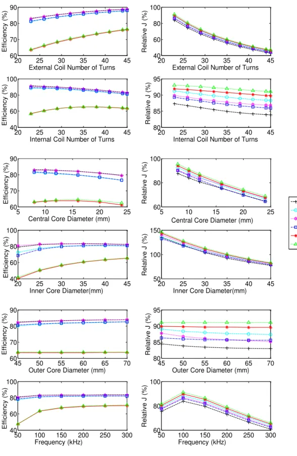
while varying the geometry according to Table I. The results are explicit in Fig. 3, which shows the
efficiency and the relative current density as functions of each dimension for all core types.
Note that the worst configuration is when the coil has no magnetic core – the relative current
density is the highest and the efficiency is one of the smallest. The configuration with core type V is
as bad as coreless, since this type of core entails in low efficiency (some cases even lower than
coreless) and the relative current density induced in the skin from this kind of core is one of the worst.
From Fig. 3, the most recommended type of core is number I, which implies the best values of
efficiency and lowest values of relative current density. All the other type of cores (II, III and IV) has
similar performance with comparable values of efficiency for any size of geometry.
It is also possible to observe in Fig. 3 that when the coils are aligned, the efficiency improves for
most of the core types while:
(a) Increasing the number of external turns.
(b) Decreasing the number of internal turns. Although for core type V and coreless coils, the
efficiency increases a little bit up to 35 turns and then starts decreasing again, for the other
types of core, the efficiency improves with less turns in the internal coil.
(c) Decreasing the size of the central core diameter. Observe that as the central core diameter
tends to zero, core type I looks similar to core type IV. However there is a conceptual
difference: making the central core diameter of core type I tend to zero means the windings
must have central diameter tending to zero, what is very difficult to obtain. Core type IV has
no core in the center of the windings, yet it has internal diameter different than zero. Thus, Fig.
3 shows that core type I is the best core type and has better results as the central core diameter
Fig. 3. Performance of TET with different geometry types and sizes. Each graphic is the variation of one of the parameters while the other parameters remain with the default value, i.e., frequency of 100 kHz, outer core diameter of 50 mm, inner
core diameter with 40 mm, central core diameter with 10 mm, internal coil with 45 turns and external coil with 23 turns.
20 25 30 35 40 45
60 70 80 90 Ef fic ien c y (%)
External Coil Number of Turns
20 25 30 35 40 45 40 60 80 100 R ela tiv e J (%)
External Coil Number of Turns
20 25 30 35 40 45 40 60 80 100 Ef fic ien c y (%)
Internal Coil Number of Turns 20 25 30 35 40 45 80 85 90 95 R ela tiv e J (%)
Internal Coil Number of Turns
5 10 15 20 25
60 70 80 90 Ef fic ien c y (%)
Central Core Diameter (mm)
5 10 15 20 25
60 80 100 R ela tiv e J (%)
Central Core Diameter (mm)
20 25 30 35 40 45 40 60 80 100 Ef fic ien c y (%)
Inner Core Diameter(mm)
20 25 30 35 40 45 50 100 150 R ela tiv e J (%)
Inner Core Diameter(mm)
45 50 55 60 65 70 60 70 80 90 Ef fic ien c y (%)
Outer Core Diameter (mm) 45 50 55 60 65 70 80 85 90 95 R ela tiv e J (%)
Outer Core Diameter (mm)
50 100 150 200 250 300 40 60 80 100 Ef fic ien c y (%) Frequency (kHz)
(d) Having the inner core diameter between 25 mm and 40 mm (though with values out of this
range, the efficiency is not much worse). Note that for core type V and coreless coils, the
bigger the inner core diameter is, the higher the efficiency is. The meaning of this parameter
for coreless TET comes from the spacing between the turns of the coil. This observation shows
that the wider the coreless coil is made, the more efficient power it will transfer.
(e) Increasing the outer core diameter. This parameter has no meaning for the coreless TET and
very little influence on core type V. This is the reason why, for those geometries, the efficiency
and induced current are constant with the change of this parameter.
(f) Increasing the frequency. Though for frequencies higher than 100 kHz, the improvement of
efficiency is negligible, the relative current density decreases at higher frequencies, having its
worst value at 100 kHz for the default configuration shown in Table I.
The behavior of the relative current density improves while:
(a) Increasing the number of external and internal turns.
(b) Increasing the size of the central and inner core diameter.
(c) Increasing the frequency, having its worst value when the frequency is 100 kHz. Here, there is
a strong relation to the conductivity of the biologic tissues. As the frequency increases, the
conductivity of the biologic tissues also increases, increasing the induced current. Looking at
Table II, it is possible to notice that the increase rate of the tissue conductivity is smaller after
100 kHz. Since the limit allowed by ICNIRP increases linearly with frequency, the relative
current density becomes smaller for frequencies at which the tissue conductivity increasing
rate is smaller (at 100 kHz).
The variation of the outer core diameter did not change the value of the relative current density.
Note that changing most of the parameter to improve the efficiency induces more current density in
the body of the patient. That could suggest a multi-objective optimization, what is not the scope of
this paper.
In addition to the core geometry, different core permeability was also analyzed for the different
types of geometry. Similarly, the results identify the core type I as the recommended type. Moreover,
Fig. 4 shows that the relative permeability of the material of the core affects very little the efficiency
of the TET for values above 50, which means that the use of materials different than ferrite with lower
relative permeability but still higher than 50 could be pertinent.
The behavior of the different core types with the variation of the thickness of the core was also
analyzed, observing that the values of efficiency and relative current density were almost the same for
all simulated thickness and the behavior with the change of core is similar to what is observed with
Fig. 4. Response of the TET with different core material and type.
The evaluation of efficiency and relative current density with variation of core permeability was
performed by varying the permeability of both internal and external cores. Thus, the behavior of all
core types might tend to the same when the relative permeability is tending to zero, what would be the
configuration with coreless coils. Since type I was appointed as the best core, it was simulated with
different relative permeability of each core, keeping the permeability of the other core constant at low
value of 20, as shown in Fig. 5.
Fig. 5. Variation of the relative permeability only in one of the cores, keeping the other core with relative permeability = 20 (Simulation only for type I)
Note that, when the external core relative permeability is constant at low value, the variation of the
internal core relative permeability almost does not change the behavior of the system. However, when
the internal core has low constant relative permeability, the curve of Fig. 5 is similar to the curve of
type I from Fig. 4. That means that the effect observed in Fig. 4 is mainly due to the variations on the
relative permeability of the external core. This observation suggests a configuration where the internal
coil has very low permeability (eventually even no core) and the external coil has a core type I with
100 101 102 103 104
80 85 90 95
R
ela
tiv
e
J
(%)
Core Permeability
100 101 102 103 104
60 70 80 90
Ef
fic
ien
c
y
(%)
Core Permeability
Type I Type II Type III Type IV Type V
101 102 103 104
78 80 82 84
Ef
fic
ien
c
y
(%)
Core Permeability
101 102 103 104
83 84 85 86
R
ela
tiv
e
J
(%)
Core Permeability
permeability bigger than 50.
B. Evaluating stability with misalignment
Seeking to analyze the behavior of the TET when the external coil is not aligned with the internal
coil, simulations with core type I (the most recommended configuration from the previous item), 45
turns in the primary coil and 23 turns in the secondary coil were performed.
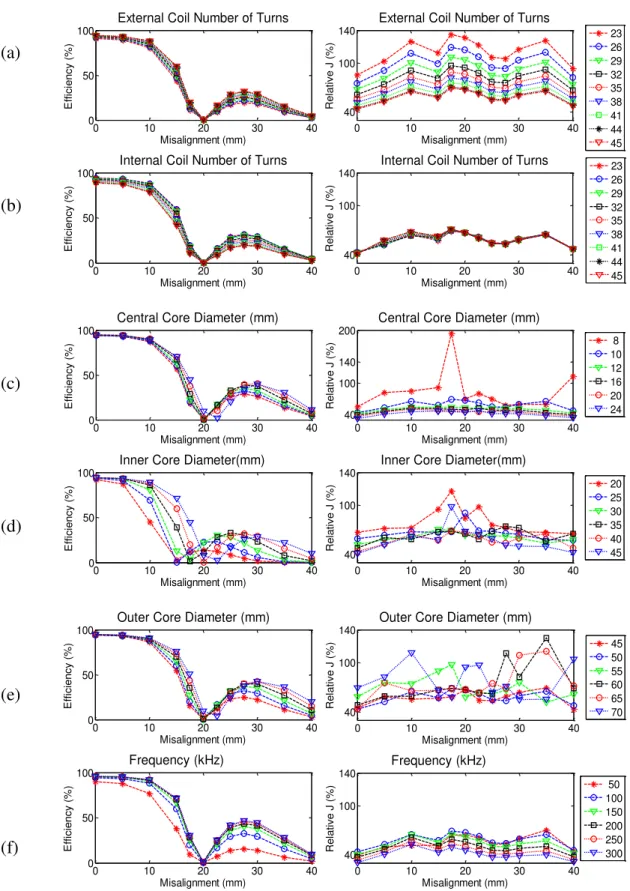
Fig. 6 shows the results of those simulations, presenting the response of the efficiency and relative
current density for the misalignment at all the configurations in the range depicted by Table I.
Observe that the default values from Table I are still the same except for the primary and secondary
number of turns which are now 45 and 23, respectively.
It can be seen that, regardless of the change of the geometry size, the efficiency declines about 20%
when the misalignment is up to 10 mm and then sinks to very low values for misalignments up to 20
mm. By further increasing the misalignments, the efficiency slightly improves, stabilizing at similar
values between 25 and 30 mm. Above 30 mm of misalignment, the efficiency devaluates again.
The declination of the efficiency is strongly influenced by the size of the internal core diameter. By
analyzing Fig. 6(d), the efficiency improves at different values of misalignment depending on the size
of the inner core diameter. If it is too small, the efficiency worsens even with misalignments smaller
than 10mm. Observe that, when the inner diameter is 20 mm, the TET reduces its efficiencies in about
40% by increasing its misalignment from 5 to 10 mm. This shows that the inner core diameter is
determinant in the stability of the TET.
Different than the efficiency, in most of the cases, the relative current density deteriorates greatly
with small misalignments of approximately 5 mm and then varies slightly with bigger misalignments,
even improving at larger misalignments. It is not easy to find a pattern on the behavior of the relative
current density. However, Fig. 6 shows that for misalignment of 17.5 mm, the relative current density
is extremely high – the highest for most of the simulated configurations. Despite this value of
misalignment, observe that the variation on the relative current density follows the same trend
independent of the number of turns in the internal and external coils, frequency, and central core
diameter. This similar trend cannot be observed when varying the inner and outer core diameter.
Indeed, Fig. 6(d) and Fig. 6(e) show different curves following different trends depending on the size
of the inner and outer core diameter.
This behavior can be understood by analyzing the chosen geometry at some specific misalignment
positions. For better perception, Fig. 7 shows the qualitative effect of the induced current density in
the skin for the default values of the dimensions when the coils are aligned and misaligned at the
Observe that, when the coils are aligned, it makes the best coupling for this application, thus lower
induced current and higher efficiency are expected. When the misalignment starts, the coupling starts Fig. 6. Response of TET to the misalignment between coils at each configuration. (external coil = 45 turns; internal coil
= 23 turns).
0 10 20 30 40
0 50 100
External Coil Number of Turns
E ff ici e n cy (% ) Misalignment (mm)
0 10 20 30 40
40 100 140
External Coil Number of Turns
R e la ti ve J (% ) Misalignment (mm) 23 26 29 32 35 38 41 44 45
0 10 20 30 40
0 50 100
Internal Coil Number of Turns
E ff ici e n cy (% ) Misalignment (mm)
0 10 20 30 40
40 100 140
Internal Coil Number of Turns
R e la ti ve J (% ) Misalignment (mm) 23 26 29 32 35 38 41 44 45
0 10 20 30 40
0 50 100
Central Core Diameter (mm)
E ff ici e n cy (% ) Misalignment (mm)
0 10 20 30 40
40 100 140 200
Central Core Diameter (mm)
R e la ti ve J (% ) Misalignment (mm) 8 10 12 16 20 24
0 10 20 30 40
0 50 100
Inner Core Diameter(mm)
E ff ici e n cy (% ) Misalignment (mm)
0 10 20 30 40
40 100 140
Inner Core Diameter(mm)
R e la ti ve J (% ) Misalignment (mm) 20 25 30 35 40 45
0 10 20 30 40
0 50 100
Outer Core Diameter (mm)
E ff ici e n cy (% ) Misalignment (mm)
0 10 20 30 40
40 100 140
Outer Core Diameter (mm)
R e la ti ve J (% ) Misalignment (mm) 45 50 55 60 65 70
0 10 20 30 40
0 50 100 Frequency (kHz) E ff ici e n cy (% ) Misalignment (mm)
0 10 20 30 40
weakening thus worsening the efficiency and the current density induced in the skin. When it is just
after 10 mm, the external core has just finished facing the internal core, as shown in Fig. 7(b). For this
reason, it is expected that the efficiency and relative current density at the skin deteriorate more by
increasing this misalignment.
Nevertheless, as the central part of the primary core loses connection with the central part of the
secondary core, it gets closer to make a better coupling with the outside edges (defined by the area
between the inner and outer diameter). When the misalignment is close to 17.5 mm the central part
begins to align with the outside edges, as shown in Fig. 7(c). Thus, the TET start having a different
new magnetic circuit with smaller reluctance and consequently, an improvement in the TET's
performance is expected as can be observed in Fig. 6 and Fig. 7.
Fig. 7. Isovalues of the Induced Current Density when the coils are with different misaligning situations, such as (a) 0 mm; (b) 10 mm; (c) 17.5 mm; (d) 30 mm. TET with 45 turns in the primary supplied by 24 V at 100 kHz and 23 turns in the secondary connected to a resistance of 18.75. Primary and secondary coils contain core type I with relative permeability
3000, 10 mm in the central core diameter, 40 mm in the inner diameter and 50 mm in the outer diameter.
While the central part of the primary core is aligned with any magnetic part of the secondary core,
the values of the efficiency should maintain similar values, depreciating again when the primary loses
(a) 0 mm
(b) 10 mm
(c) 17.5 mm
magnetic coupling with the secondary, what happens at 30 mm. This explanation also justifies why
the worst values of relative current density occur when the internal core diameter is smaller than 30
mm or larger than 45 mm, what can be observed in Fig. 6 by analyzing the performance of the TET
with the change of the internal core diameter.
It is noteworthy to mention that the value of the current density is exceeding the limit established by
ICNIRP when the coils are misaligned only for some configurations, mainly when the external coil
has less than 32 turns.
Moreover, it can be concluded that the outer core diameter should not be larger than 55 mm,
because such configurations entail in higher relative current density, even though better values are
achieved when the misalignment is 17.5 mm. It is noteworthy to remember that, these analyzes are
being performed only for core type I, as mentioned in the beginning of this section.
In addition to this analysis with geometric dimensions, this paper also studied the sensitivity of the
efficiency and induced current density at configurations with different core permeability in the range
described by Table I. Fig. 8 shows this result.
Fig. 8. Response of TET to the misalignment between coils at each simulated permeability. (TET with 45 turns in the primary supplied by 24 V at 100 kHz and 23 turns in the secondary connected to a resistance of 18.75. Primary and secondary coils contain core type I with relative permeability 3000, 10 mm in the central core diameter, 40 mm in the inner
diameter and 50 mm in the outer diameter.).
From Fig. 8, the efficiency changes with the misalignment in the same way for core relative
permeability above 30. For core permeability smaller than 30, the sensitivity of the efficiency with
respect to the misalignment is slightly different, affecting more the efficiency at misalignments higher
than 20 mm.
Regarding the relative induced current density, it has the highest variations with the misalignment
as the core permeability has the lowest values. This means that the lower the core permeability is, the
more sensitive the induced current density is to misalignments.
0 5 10 15 20 25
0 50
100 Core Permeability
E
ff
ici
e
n
cy (
%
)
Misalignment (mm)
0 5 10 15 20 25
40 60
80 Core Permeability
R
e
la
tive
J
(%
)
Misalignment (mm)
V. CONCLUSIONS
This paper made a comparison among the performances of different types of core geometry of
TETs and realized that the use of round core with the flat coil inserted in the core, type I, brings the
best efficiency at the lowest values of relative induced current density, what is one of the constraints
for a safe use of the device.
This conclusion was also observed when comparing the different geometries with different
permeability of the material, what makes this type of geometry possible to be built even with
materials that are not Ferrite, such as plastic ferrites or magnetorheological fluids [10].
In addition, this paper made a more thorough analysis in this recommended option, investigating the
behavior of this configuration in different sizes and for different positions of misalignment between
the coils. It could be observed that:
• The stability of the efficiency is strongly dependent on the inner core diameter, getting worse as the diameter gets smaller.
• In order not to exceed the limits of the induced current density in the skin in the analyzed cases, the default external coil must have more than 32 turns if the internal core has 23 turns.
• The core relative permeability does not affect much the efficiency for values above 50, but the induced current density is as sensitive to misalignments as the core relative permeability is lower.
Thus, the use of new materials with core relative permeability as low as 50 is acceptable in this case.
The performance of the TET with misalignments were detailed, explaining the reasons of change in
the trend at some specific positions and indicating that this particular TET should not be misplaced by
more than 15 mm.
ACKNOWLEDGMENT
The authors would like to thank Prof. Florent Morel from the Ecole Centrale de Lyon for his
revision and suggestions. Moreover, the authors would like to thank the support from Sao Paulo
Research Foundation (FAPESP) under grant 2011/18341-3 and National Council of Scientific and
Technologic Development of Brazil, CNPq, under grant 309350/2012-3/PQ.
REFERENCES
[1] J. Ma, Q. Yang, and H. Chen, “Transcutaneous Energy and Information Transmission System with Optimized
Transformer Parameters for the Artificial Heart”, IEEE Transactions On Applied Superconductivity, vol. 20, no. 3, pp. 798-801, 2010.
[2] H. Miura, S. Arai, Y. Kakybari, F. Sato, H. Matsuki, and T. Sato, “Improvement of the transcutaneous energy
transmission system utilizing ferrite cored coils for Artificial Hearts”, IEEE Transactions On Magnetics, v.42, no. 10, pp. 3578-3580, 2006.
[3] H. Matsuki, M. Shiiki, K. Murakami, and T. Yamamoto, “Investigation of Coil Geometry for Transcutaneous Energy
Transmission for Artificial Heart”, IEEE Transactions on Magnetics, vol. 28, no. 5, pp. 2406-2408, 1992. [4] G. E. Miller, “Artificial Organs” (VA, USA. Morgan & Claypool publishers, 2006).
[5] C. M. Zierhofer, and E. S. Hochmair, “Geometric approach for coupling enhancement of magnetically coupled coils”, IEEE Transactions on Biomedical Engineering, vol. 43, no. 7, 1996.
[6] Institute for Applied Physics Nello Carrara. An Internet resource for the calculation of the dielectric properties of the body tissues in the frequency range 10 Hz–100 GHz. http://niremf.ifac.cnr.it/tissprop/.
[8] ICNIRP (International Commission on Non-Ionizing Radiation Protection), “Guidelines for Limiting Exposure to Time-Varying Electric, Magnetic, and Electromagnetic Fields (up to 300 GHz)”. Health Physics, 74(4), 1998, 494–522. [9] J. Jin, “The Finite Element Method in Electromagnetics”, John Wiley & Sons, Inc., 2nd edition, 2003.
[10]T. M. Simon, F. Reitich, M. R. Jolly, K. Ito, H. T. Banks, “Estimation of the Effective Permeability in