Response of vertical pile group subjected to horizontal cyclic
load in soft clay
Abstract
The environment prevalent in ocean necessitates the piles supporting offshore structures to be designed against lateral cyclic loading initiated by wave action. Such quasi-static load reversal induces deterioration in the strength and stiff-ness of the soil-pile system introducing progressive reduction in the bearing capacity as well as the pile head displacement. To understand the effect of lateral cyclic load on lateral ca-pacity of pile group in soft clay, a series of laboratory exper-iments were performed on model piles in soft cohesive soil. This paper presents the experimental observations made and the relevant conclusions drawn there from.
Keywords
pile group, cyclic load, clay, frequency, amplitude.
S. Basack∗
Associate Professor of Applied Mechanics, Bengal Engineering & Science University, Howrah-711103 – India
Received 6 May 2009; In revised form 9 Mar 2010
∗Author email: [email protected]
1 INTRODUCTION
Offshore structures, namely, oil drilling platforms, jetties, tension leg platforms etc. are mostly supported on pile foundations. Apart from the usual super structure load (dead load, live load, etc.), these piles are subjected to continuous lateral cyclic loading resulting from ocean waves. As reported by other researchers, this type of loading induces progressive degradation of the foundation capacity associated with increased pile head displacement. The following are the reasons primarily responsible for such degradation of strength and stiffness of the pile-soil systems : (i) Development of excess pore water pressure generated during cyclic loading in progress. (ii) General accumulation of irrecoverable plastic deformation of soil surrounding the pile surface. (iii) Rearrangement and realignment of soil particles surrounding the pile surface.
The lateral cyclic loading may be under load-controlled mode or displacement-controlled mode. In former case, the load applied at the pile head varies cyclically with time such that the maximum and the minimum values remain constant for all cycles. In the later case, it is the pile head deflection and not the applied load, which varies cyclically with time such that the maximum and the minimum values remain constant for all cycles.
investigation reported herein is to carry out experimental investigation so as to understand the effect of lateral cyclic loading on the performance of pile foundation in soft clay.
2 OBJECTIVE
Considerable investigations have already been carried out in the related field of research. Amongst significant contributions, the works of Matlock [6], Reese [16, 17], Poulos [9, 10], Purkayastha & Dey [12], Narasimha Raoet al. [15], Jardine & Chow [5], Dyson [3], Randolph [14] and Goudin & Lehane [4] are worthy of note. While some investigations are theoretical, the others have been experimental (laboratory and/or field) works. From a brief review of these works, it may be concluded that : (i) Under the action of lateral cyclic loading, the ultimate capacity of pile foundation alters. (ii) Such alteration is dependant not only on the soil properties and pile geometry, but also on the cyclic loading parameters, i.e., number of cycles, frequency and amplitude. Moreover, investigations on the behaviour of pile group under lateral cyclic load in soft clay are quite limited.
Hence, the primary objective of the present work reported herein is to carry out experi-mentations so as to understand the behaviour of pile group under lateral cyclic load in soft cohesive soil. Particularly, observations are made to study how the alteration in ultimate pile capacity is being affected by cyclic loading parameters and pile head conditions. It is hereby mentioned that the alteration in pile capacity, as stated above, has been represented by a non-dimensional term ‘Degradation Factor’ which is defined as the post-cyclic to pre-cyclic ultimate pile capacities, as per Purkayastha & Dey [12].
3 SOIL AND PILE
3.1 Soil
Kaolin powder available from local market was mixed with water and this mixture was used for preparing the bed of soft cohesive soil. The soil was light yellowish in colour. Hydrometer test indicated that it contains 60% clay, 40 % silt and traces of sand. The liquid limit and the plastic limit of the soil were found to be 52% and 30% respectively, with the value of plasticity index as 22%. From standard Proctor compaction test, the maximum dry density of the soil was reported as 15.2 KN/m2with the optimum moisture content of 28%. The specific gravity
of a base platform to be placed on the soil surface. Compaction was acheived by repeated dropping of a weight of 60N from a height of 0.6m on the top of this platform.
3.2 Pile
Experiments were carried out using 2 x 2 pile group, each pile being hollow circular stainless steel bar having 20 mm outer diameter and 600 mm overall length. The depth of embedment was 500 mm (L/d = 20) and the lateral load was imparted at a height of 90 mm above the soil surface. In order to insert the piles easily through the soil medium, the tips of the piles were pointed in shape. The piles were threaded at the top to attach with the pile cap by means of nuts. The piles were attached to a common pile cap which was actually a 16mm thick square steel plate. The c/c distances between the piles in the group was 60 mm. (= 3d).
4 EXPERIMENTAL SET UP
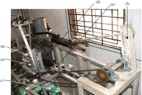
Since no standard apparatus for imparting lateral cyclic load on piles is available, a new multi-purpose set up was designed and fabricated. A photographic view and the sketch of this apparatus are shown in Fig. 1(a) & (b). The detailed description with operating principle and performance study of this test set up has been published elsewhere [2]. However, some of its important components are described below.
4.1 Test tank
A stainless steel tank was designed and manufactured for preparing the soil bed. The tank consisted of three flanged segments each having 200 mm height and 400 mm internal diameter and 5 mm wall thickness. The. flanges of the segments were provided with holes for bolting purpose. Rubber gaskets were provided between the flanges of the adjacent segments to keep the side of the tank water tight as well as soil tight. Provision had been kept at the bottom of the tank to allow drainage of water from the soil bed, whenever required.
4.2 The loading device
The loading device consisted of two separate units, one is for static loading and the other for cyclic loading, both being parallely connected with a central motor and gear system, such that one unit could be operated at a time. By chain and sprocket arrangement, each unit could be engaged or detached separately with the motor gear system.
4.3 Central motor and gear system
(d)
(e) (f)
(c) (a) (b)
Legend : (a) Test tank. (b) Pile head connector. (c) Central motor-gear system. (d) Load controlled unit. (e) Displacement controlled unit. (f) Crank shaft.
(a)
Central Motor and Gear
System
Detachable Sproket Detachable
Sproket
Displacement Controlled
Unit Load
Controlled Unit Through Chain and Sprocket
Through Connecting
Through
Pile Head Connector
Static Loading To mains
(b)
4.4 Static loading device
For static loading test, the apparatus was designed in such a manner that the strain controlled loading could be applied at the pile head, where the pile was pushed forward at a constant rate of horizontal displacement. By measuring the applied lateral load and the corresponding horizontal deflection of pile cap, the lateral load-deflection curves were plotted.
To serve this purpose, three shafts were connected in series between the output point of the central motor and gear system by means of bevel gears. The end shaft was threaded throughout its length to provide the forward and back ward motion of the holder. At one end, the end shaft is attached with a bevel gear and the other end with a holder wich was welded on the top of a sliding unit. This sliding uniot was connected to the pile head connector through a load cell.
4.5 Cyclic loading device
The experimental set up was designed in such a manner that the cyclic loading test could be performed under both the displacement controlled and the load controlled modes. The units for the same were connected in parallel between the pile head and the motor gear system such that one unit could be operated at a time. An adjustable differential cam mechanism was attached in parallel with the central motor gear unit to convert the rotation to horizontal sinusoidal translation, which was finally be applied on the pile head. The adjustable cam-shaft was uniquely designed to get different cyclic displacement amplitudes. The load controlled cyclic loading device, on the other hand, was capable of providing a two-way lateral cyclic load about a zero mean value. It consisted of an oscillating arm supported on a single point joint. At the bottom of the arm a semi-circlular pinion was fixed which was attached with a rack. The other end of the rack was connected to the pile head through load cell. A movable weight could slide over the oscillating arm keeping the pin joint as mean. The weight was provided over the oscillating arm by means of a cylindrical stainless steel container in which different weight blocks could be placed The motion from the main shaft to the crank was provided by means of chain and sprocket arrangement.
4.6 Ancilliary equipments
rigidly fixed with the pile head by threads. (vi) Pile Driving Unit: To insert the pile into the soil bed a screw-jack type arrangement was fabricated. It could be operated by a driving wheel. (vii) Mechanical Counter: To measure the applied number of cycles, a mechanical counter was attached to the main shaft.
-4 -3 -2 -1 0 1 2 3 4
-4 -3 -2 -1 0 1 2 3 4
Imposed (kg)
D
ig
it
a
l
In
d
ic
a
to
r
R
e
a
d
in
g
(
k
g
)
Compression
Tension
Figure 2 Calibration curve of the load cell.
5 TEST PROCEDURE AND PROGRAM
5.1 Test procedure
The testing were done following a definite sequential procedure as described below:
1. After the preparation of test bed following the procedure mentioned in the preceding section, the pile group was inserted into the bed by slowly rotating the driving wheel of the pile-driving unit. The pile head was then bolted rigidly with the pile head connector.
2. The pile head connector was then connected either with the load controlled unit or with displacement controlled unit depending on the experimental mode.
3. Next, the desired load amplitude in case of load controlled test or displacement ampli-tude in case of displacement controlled test were set as per the desired ampliampli-tude. The frequency was also set to the desired magnitude.
4. The motor was then started. It was stopped after the desired number of cycle was attained.
5. Then the load controlled or the displacement controlled unit was disengaged from the pile head connector and the static loading unit was engaged to the power shaft through the load cell placed in between them.
7. The machine was started again. The load and the pile head displacements were recorded at regular interval upto about 8 mm lateral deflection of pile cap (about 40% of the pile diameter9)
8. For each test separate soil bed was prepared.
5.2 Test program
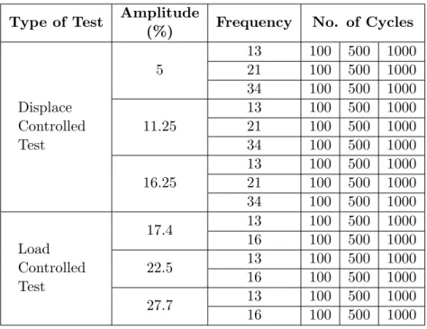
The experiments were conducted with the test program presented in Table 1.
Table 1 Experimental program for clay.
Type of Test Amplitude Frequency No. of Cycles (%)
Displace Controlled Test
5
13 100 500 1000
21 100 500 1000
34 100 500 1000
11.25
13 100 500 1000
21 100 500 1000
34 100 500 1000
16.25
13 100 500 1000
21 100 500 1000
34 100 500 1000
Load Controlled Test
17.4 13 100 500 1000
16 100 500 1000
22.5 13 100 500 1000
16 100 500 1000
27.7 13 100 500 1000
16 100 500 1000
6 RESULTS AND DISCUSSIONS
The load applied on the pile group has been expressed in non-dimensional form by dividing the same by cud2, where ‘cu’ is the unit cohesion of the soil and ‘d’ is the pile diameter. Similarly, the pile head displacement is expressed as a percentage of pile diameter. In case of load controlled mode of cyclic loading, the amplitude has been normalized by ultimate static lateral pile capacity. On the other hand, for displacement controlled mode, the amplitude is normalized by pile diameter.
6.1 Experimental observation
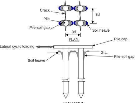
cracks. Also a heave of soil was developed around the pile. This is illustrated in Fig. 3.
G.L. 3d
3d
PLAN.
Crack
Pile
Pile-soil gap
Pile cap.
Pile-soil gap. Lateral cyclic loading
ELEVATION.
Soil heave
Soil heave
Figure 3 A diagram showing the gap formation around the pile group in the vicinity of soil surface during cyclic loading in progress.
6.2 Effect of scaling
In order to investigate true behaviour of foundation, the most direct way is to conduct field scale experiments. Since it is not always economical or practical, especially for cyclic loading on piles, the alternative is to use smaller scale models. To represent the prototype conditions fully, however, it is necessary to recreate both the in-situ stress gradient and history which is particularly important for piles loaded laterally where much of the load transfer occurs in upper few metres of soil. It is worth mentioning that the ideal instrument for conducting this type of model testing is the geotechnical centrifuge where the package of soil, the model and other equipments are spin about a fixed axis and the radial acceleration so produced is several times the gravitational acceleration ‘g’. However, in absence of such facilities in the laboratory, the model tests in the acceleration field of 1g were conducted by many researchers, e.g., Purkayastha & Meyerhof [13], Narasimha Raoet al. [15], Douri & Poulos [1], etc.
6.3 Load deflection curves
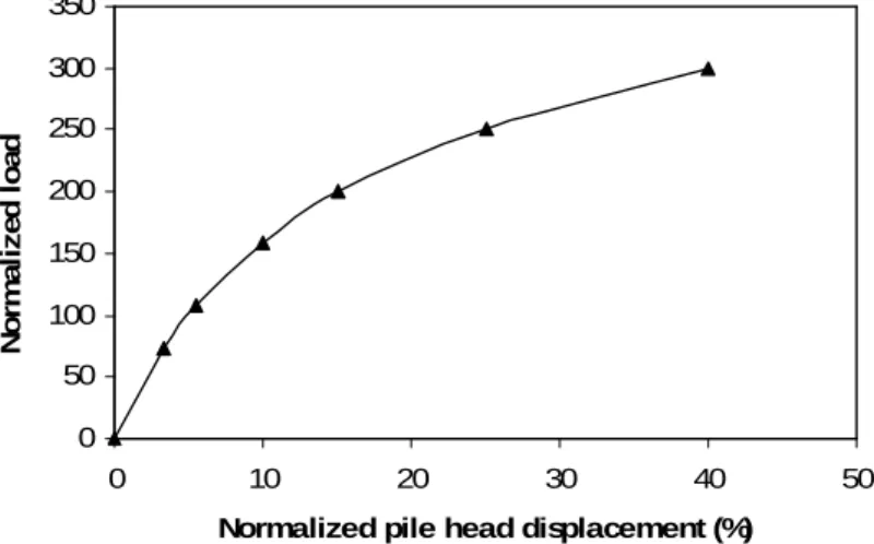
The load deflection response of the pile group in the soft clay soil was found to be hyperbolic in nature. The ultimate capacities were estimated by double tangent method. The pre-cyclic load deflection curve is shown in Fig. 4, from which the static lateral capacity of the pile group was evaluated as 400 N. A typical post cyclic load-defection curve is shown in Fig. 5.
0 50 100 150 200 250 300 350
0 10 20 30 40 50
Normalized pile head displacement (%)
N
o
rm
a
li
z
e
d
l
o
a
d
Figure 4 Pre-cyclic static load-deflection curve.
0 10 20 30 40 50
0 2 4 6 8 10
P ile Head Deflection (mm)
L
a
te
ra
l
L
o
a
d
(
K
g
)
100 500 1000 No. of cycles :
Load controlled test. Frequency : 16 c.p.m. Amplitude : 22.5 %.
Figure 5 A post-cyclic load-defection curve.
6.4 Ultimate lateral capacities and degradation factors
the degradation factors were calculated. The values of experimental degradation factors of the pile groups in the kaolin bed under displacement control and load control modes of testing are given in Tables 2 & 3 respectively. It should be mentioned at this stage that the theoretical values of the cyclic ultimate lateral capacities were estimated with the help of the following the relation as proposed originally by Purkayastha & Dey [12]:
HU C=HU S×DF
Where,
HU C: Theoretical cyclic ultimate lateral capacity of the pile group.
HU S: Theoretical static lateral capacity of the pile group, calculated using the standard method suggested by Poulos & Davis [11] and Meyerhof & Adams [7].
DF: Experimental degradation factor.
The above relation has been used to evaluate the theoretical lateral cyclic capacities of pile groups at various no. of cycles, frequencies and amplitudes. The theoretical static lateral ultimate capacity of the pile group was evaluated as 505N against the experimental value of 400 N.
Table 2 Experimental degradation factors under displacement controlled tests.
No. Of Cycles
Amplitude (%):
5.00 11.25 16.25
Frequency (c.p.m.): Frequency (c.p.m.): Frequency (c.p.m.):
13 21 34 13 21 34 13 21 34
100 0.849 0.928 0.969 0.763 0.841 0.887 0.640 0.722 0.784
500 0.722 0.784 0.835 0.619 0.660 0.742 0.590 0.619 0.650
1000 0.660 0.742 0.784 0.546 0.639 0.660 0.501 0.558 0.619
Table 3 Experimental degradation factors under load-controlled tests.
No. Of Cycles
Amplitude (%):
17.40 22.50 27.70
Frequency (c.p.m.): Frequency (c.p.m.): Frequency (c.p.m.):
13 16 13 16 13 16
100 0.722 0.742 0.640 0.711 0.594 0.619
500 0.680 0.701 0.598 0.652 0.549 0.577
6.5 Variation of ultimate cyclic pile capacities with cyclic loading parameters
The values of ultimate cyclic pile capacities were plotted against the no. of cycles. Fig. 6 shows a typical plot. It was observed that the ultimate cyclic pile capacities non-linearly decreased with no. of cycle with a tendency of asymptotic stabilisation.
225 325 425 525
0 400 800
No of Cycles
N o rm a li z e d p il e c a p a c it y . 13(test) 21(test) 24(test) 13(theory) 21(theory) 24(theory) 300 200 100 0
Displacement Controlled Test Amplitude: 5%
Frequency (c.p.m.) :
Figure 6 A typical variation of ultimate lateral pile capacity with no. of cycles.
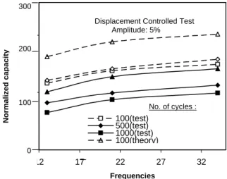
The ultimate cyclic pile capacities were also plotted against frequency. A representative plot is shown in Fig. 7. ultimate cyclic pile capacities were observed to increase with frequency with an asymptotic stabilizing tendency.
200 375 550
12 17 22 27 32
Frequencies N o rm a li z e d p il e c a p a c it y . 100(test) 500(test) 1000(test) 100(theory) 500(theory)
No. of cycles : Displacement Controlled Test Amplitude: 5% 300 200 100 0 N o rm a li z e d c a p a c it y
Figure 7 A typical variation of ultimate lateral pile capacity with frequency.
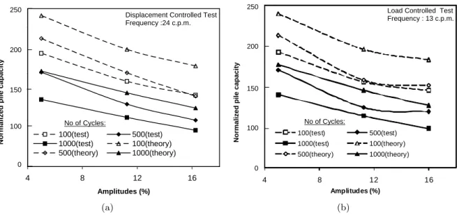
160 260 360 460
4 8 12 16
Amplitudes (%) N o rm a li z e d p il e c a p a c it y . 100(test) 500(test) 1000(test) 100(theory) 500(theory) 1000(theory) 250 200 150 100 0
No of Cycles:
Displacement Controlled Test Frequency :24 c.p.m.
(a)
175 295 415 535
4 8 12 16
N o rm a li z e d p il e c a p a c it y .
Amplitudes (%) .
100(test) 500(test)
1000(test) 100(theory)
500(theory) 1000(theory)
Load Controlled Test Frequency : 13 c.p.m.
No of Cycles: 250 200 150 100 0 N o rm a li z e d p il e c a p a c it y (b)
Figure 8 A typical variation of ultimate lateral pile capacity with amplitude for: (a) displacement-controlled test. (b) load controlled test.
7 CONCLUSIONS
From the entire investigation, it has been observed that under the effect of lateral cyclic loading on pile groups in soft clay, the pile capacity deteriorates. This alteration was represented by ‘degradation factor’, a non-dimensional quantity given by the ratio of post-cyclic to pre-cyclic ultimate lateral pile capacities. Other researchers in the related field of investigation have found that the ultimate cyclic pile capacity and the degradation factors were observed to vary with number of cycles, frequency and amplitude of cyclic loading, but the pattern of variation have not been investigated in details. The attention of present study is focussed to bridge this gap. From experiments, it was observed that the ultimate cyclic pile capacity as well as the degradation factors decreased with no. of cycles and increased with frequency non-linearly having a tendency of asymptotic stabilization. With amplitude, the parameter was found to decrease non-linearly, but no definite pattern of variation could be noted.
Based on the above experimental observations, the author is carrying out further research in this area including theoretical analysis and development of a design methodology for piles in soft clay under lateral cyclic. The outcome is beyond the scope of this paper and will be published elsewhere.
References
[1] Riadh H. AL-Douri and H. G. Poulos. Predicted and observed cyclic performance of piles in calcereous sand.Journal
of geotechnical engineering, 121(1), 1995.
[2] S. Basack. A technical note on development and performance study of an apparatus for imparting lateral cyclic load on pile foundation.Marine georesources and geotechnology, 27(3), 2009.
[3] G. J. Dyson.Lateral loading of piles in calcareous sediments. PhD thesis, Department of Civil & Resource Engineer-ing, University of Western Australia, Perth, Australia, 1999.
[4] C. Goudin and B.M. Lehane. A centrifuge study of monotonic and cyclic resistance of piles and pile groups in sand.
InInternational Symposium on Frontiers in Geotechnical Engg., Perth, Australia, 2005.
[5] R. J. Jardine and F. C. Chow. New design methods for offshore piles. Technical Report Publication 96/103, Department of Civil Engineering, Imperial College, London, U.K., 1996.
[6] H. Matlock. Correlations for design of laterally loaded piles in soft clay. In Proceedings of 2nd Offshore Technical
Conference, Houston, 1970. Paper No. OTC 1204.
[7] G.G. Meyerhof and J.I. Adams. The ultimate uplift capacity of foundations. Canadian geotechnical journal, 5(4), 1968.
[8] N. K. Oveseen. The scaling law relationship – panel discussion. InProceedings, 7th European conference on soil
mechanics and foundation engineering, no.4, 1979.
[9] H. G. Poulos. Some aspects of skin friction of piles in clay under cyclic loading. Journal of soil mechanics &
foundation, ASCE, 12(1), 1981.
[10] H. G. Poulos. Single pile response to lateral cyclic load. Journal of geotechnical engineering, ASCE, 108(GT-3), 1982.
[11] H. G. Poulos and E. H. Davis.Pile foundation analysis and design. John wiley & sons, New York, 1980.
[12] R. D. Purkayastha and S. Dey. Behavior of cyclically loaded model piles in soft clay. In2nd international conference
on recent advances in geotechnical earthquake engineering and soil dynamics, University of Missouri-Rolla, 1991.
[13] R. D. Purkayastha and G. G. Meyerhof. Bearing capacity of rigid piles under eccentric loads in a layered soil.Indian
geotechnical journal, 15(3), 1985.
[14] M. F. Randolph. Ratz version 4-2: load transfer analysis of axially loaded piles. Technical report, School of civil and resource engineering, University of western australia, Perth, Australia, 2003.
[15] S. Narasimha Rao, Y. V. S. N. Prasad, and C. Veeresh. Behavior of embedded model screw anchors in soft clays.
Geotechnique, 43(4), 1993.
[16] L. C. Reese. Laterally loaded piles: programme documentation.Journal of geotechnical engineering division, ASCE, 103(GT-4), 1977.
[17] L. C. Reese, W. R. Cox, and F. D. Coop. Analysis of laterally loaded piles in sand. In6th annual offshore technology
conference, Houston, 1974. paper OTC 2080.
[18] A. N. Schofield. Cambridge university geotechnical centrifuge operation: Rankine lecture.Geotechnique, 30(3), 1980.
[19] R. N. Taylor. Centrifuges in modelling: principles and scaling effects. Geotechnical centrifuge technology, Blackie