Abstract— This paper presents an optically controlled reconfigurable antenna for millimetre-wave frequency range. Silicon switches are used to control the optical reconfiguration, modifying the frequency response and radiation pattern of the antenna design. Therefore, the system can switch between the lightly licensed 28 GHz and 38 GHz frequency bands, useful for future mobile 5G broadband cellular communication networks. Experimental results with the reconfigurable antenna on 16-QAM and 32-QAM wireless transmission supported by photonic downconversion are successfully reported under 78 dB link budget requirement.
Index Terms— Hybrid optical-wireless architecture; optical reconfiguration; reconfigurable antennas; slotted waveguide antenna.
I. INTRODUCTION
The number of users of wireless technology has presented a continuous up growth during the last decades, pressing the development of new technologies to supply the market necessities. The dominance of smartphone in traffic web will bring on a saturation of the current network bandwidth capacity, which operates in frequencies lower than 2.7 GHz. Therefore, higher frequency bands have being investigated for high-capacity wireless systems, especially in unlicensed or lightly licensed millimeter wave (mm-wave) frequency bands, such as: the E-band (60-90GHz), W-band (75-110 GHz) and even sub-Terahertz (100-300GHz) [1-3]. To make available these efficient broadband wireless systems, operating in different frequencies, antenna is a key component to guarantee the applicability of the signal distribution. Although optical technologies can provide solutions to generate and distribute such signals, the electrical front-ends at these frequency regimes are still under development. Moreover, distributed antenna systems architectures have been shown a promising technology, due to the reduced wireless coverage in case of mm-wave links [4].
Optically controlled reconfigurable antenna
for 5G future broadband cellular
communication networks
I. F. da Costa and D. H. Spadoti
Federal University of Itajubá, Av. BPS 1303, Itajubá-MG, Brazil. A. C. Sodré Jr. and L. G. da Silva
Laboratory WOCA (Wireless and Optical Convergent Access), National Institute of Telecommunications (Inatel), Av. João de Camargo, 510, Santa Rita do Sapucaí-MG, Brazil, 37540-000
S. Rodriguez, R. Puerta, J. J. V. Olmos and T. Monroy
A potential band which has been proposed for future 5G broadband cellular communication networks and satisfies bandwidth requirements is 28 GHz and 38 GHz frequency bands [5]. In such mm-wave bands, unlike at 60 GHz and above, atmospheric absorption does significantly not contribute to additional path loss [6]. Moreover, the development of front-ends capable of operating in both bands simultaneously is necessary to support large-scale deployments. Radio over Fiber (RoF) is a potential technology to enable the integration of wireless and fiber optic networks by means of taking advantages of the benefits of optical fiber with the mobility and ubiquity of wireless networks [7-8]. It is based on the transmission of RF signals by using an optical carrier through optical fiber links. RoF is an essential technology for the provision of untethered access to broadband wireless communications in a range of applications including last mile solutions, extension of existing radio coverage and capacity, indoor and outdoor cellular systems, among others.
With respect of the exploration of the underutilized mm-wave frequency spectrum be considered a potential candidate for future broadband cellular communication networks, there are several works published regarding propagation analysis of cellular mm-wave in densely populated environments [5,9-10]. T. Rappaport et al. have recently reported extensive propagation measurements campaigns at 28 GHz and 38 GHz bands for providing an insight on their applicability for indoor and outdoor environments in Austin and New York cities [5]. Moreover, narrowband wideband measurements have been performed in diverse indoor and outdoor environments in order to enable the development of reliable prediction models for 60 GHz radio channels [10].
On the other hand, another interesting and promising solution for the recent technologies of wireless communications systems is the use of reconfigurable antennas [11]. This class of antennas enables to reconfigure not only the bandwidth, but also the radiation pattern and polarization pattern. Reconfigurable antenna ensures flexibility design, once it presents frequency agile and makes use of software defined and cognitive radios to cope with extendable and reconfigurable multiservice, multistandard and multiband operation. Moreover, by using reconfiguration, an efficiently use of the spectrum and the power utilization is achieved. Our group has recently proposed the concept of an Adaptive and Cognitive Radio over Fiber (ACRoF) [12] based on the integration of an optically controlled reconfigurable antennas and RoF systems [13]. Using this new approach, it becomes possible to perform a high capacity optical backhaul with a broadband, energy- and spectrum-efficient wireless access segment, also exploiting new spectral resources.
system implementation, whereas Section 4 presents the experimental results of the system performance evaluation. Finally, conclusions and future works are addressed in Section 5.
II. RECONFIGURABLE ANTENNA DEVELOPMENT
This section presents the development of a high-performance antenna to be applied in the 28 GHz and 38 GHz wireless experiments. In order to satisfy the requirements of the next generations of wireless networks, an optically controlled reconfigurable and multiband slotted waveguide antenna array (OCRAA) is proposed, as shown in Fig. 1. There are several mechanisms to reconfigure the antenna structure. Particularly, optically controlled antennas have been intensely exploited in the last years due to their unique advantages, such as: easy integration to optical systems, absence of bias lines, linear behavior, very fast switching and activation without producing harmonics and intermodulation [11, 14-15].
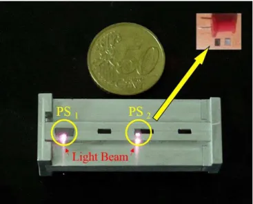
Fig. 1. Optically-controlled reconfigurable slotted-waveguide antenna developed for the experiments. In the up right corner a
photoconductive switch and its integration to the reconfigurable antenna is presented
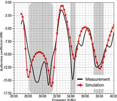
Fig. 2. Reflection coefficient with optical switch off: measured (black continuous curve) and simulated (red continuous with
triangles).
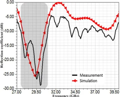
a) Reflection coefficient for the first optical switch on: measured (black continuous curve) and simulated (red continuous
with triangles).
b) Reflection coefficient for the first and second optical switch on: measured (black continuous curve) and simulated (red
continuous with triangles).
Fig. 3. OCRAA reconfigurable frequency response.
Since the feeding structure excites a wide range of frequencies inside the waveguide structure, other operation bands can couple with the slots. Therefore, the distance between the slots for 28 GHz and 38 GHz generates a third operation band around 34 GHz. This band can also be useful for the 5G networks, but for this work, just 28GHz and 38GHz bands are the interest regions.
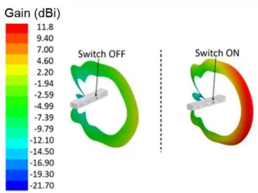
significantly modifies the antenna radiation pattern. For instance, its gain at 38 GHz increases from
-3.35 dBi on the “OFF” state (green region of the main lobe from the top part) to 11.80 dBi as soon as
the switch is turned to “ON” state (red region of the main lobe from the bottom part).
Fig. 4. Antenna radiation patterns for 38 GHz: OCRAA on “OFF” state and “ON” state.
III. SYSTEM IMPLEMENTATION
The experimental setup is presented in Fig. 5, including the photonic downconversion stage. The Radio Frequency (RF) signal is generated using a Vector Signal Generator (VSG). It provides 40 Mbaud 16-QAM or 32-QAM at RF frequencies between 28 GHz and 39 GHz. Its output is fed into the optical controlled antenna at 5.0 dBm RF power. The RF signal is transmitted through a 5 m wireless link and received by a broadband horn antenna, and amplified using a double stage, a low noise RF amplifier (LNA) with 30 dB gain and Power Amplifier (PA) with 21 dB of gain and noise figure less than 6 dB.
photodiode is amplified and sampled using a high speed Digital Signal Oscilloscope (DSO) to perform digital demodulation and Error Vector Magnitude (EVM) measurement.
Fig. 5. Experimental setup including the photonic downconversion stage. VSG: vector signal generator, CS: Current Source,
TxA: transmitting antenna, RxA: receiving antenna, PC: polarization controller, MZM: Mach-Zehnder modulator, LNA: low
noise amplifier, PA: power amplifier, EDFA: Erbium doped fiber amplifier, OBPF: Optical Band Pass Filter, VOA: variable
optical attenuator, PD: photo detector, DSO: digital storage oscilloscope; LO: local oscillator.
IV. RESULTS AND DISCUSSION
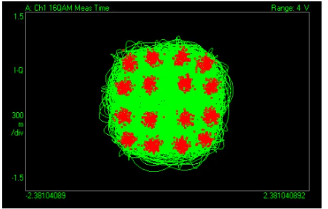
This section reports the experimental results for 16- and 32-QAM wireless transmission obtained using the developed antenna and photonic downconversion technique. Initially, it has been carried out experiments using OCRAA antennas for data transmission and one horn antenna for reception. Figure 6 presents the obtained results for a 16-QAM RF signal at 38 GHz propagated through 5 meters. The beating between the LO and RF signals measured was -14 dBm. The measured constellation is displayed in Fig. 6, in which the rms value of Error Vector Magnitude (EVMrms) is
only 3.09 %.
The main experiment has been focused on the implementation and applicability analysis of the optically controlled reconfigurable antenna. Once the used VSG can provide a higher output power level at the 39GHz, we decided to use the superior limit of the operation band, to obtain the best performance of the system. As described in Section 2, its bandwidth and radiation patter can be significantly managed by optimizing the incident optical power on the photoconductive switch. Mainly, its gain at 39 GHz can be significantly enhanced, from 2.62 dBi to 10.32 dBi, by illuminating
the photoconductive switch, i.e. turning it to “ON” state.
Another test was performed for 32-QAM transmission pattern for 39 GHz frequency, which is the upper limit of the third bandwidth from OCRAA, as presented in Fig. 2. The free-space loss, calculated by Friis Equation [21], is 78.24 dB for 39 GHz and 5 m distance. Fig.7 reports the obtained results of the performance investigation for a 32-QAM signal as a function of the electrical Signal-to-Noise Ratio (SNR) and EVMRMS. Both are plotted with respect to the applied current at the controller
laser used to reconfigure the antenna properties.
a) SNR as a function of laser current
Fig. 7. Experimental investigation of 39 GHz wireless transmission with photonic downconversion using one horn
broadband antenna and an optically controlled antenna.
The constellation has been shown extremely poor for the “off” state of photoconductive switch and, consequently, the measured EVMRMS was 12.2%. The higher is the laser current; the
better is EVMRMS, reaching 5.8% for 2.5 A. The measured constellation for “on” state is extremely
better than the “off” state, as highlighted in the top-right inset of Fig. 7b. Additionally, SNR has also
been significantly improved by 7 dB, as illustrated in Fig. 7a. These results demonstrate that the frequency-agile and optically steerable antenna properties can be efficiently applied to implement an adaptive wireless system in the mm-wave frequency range.
V. CONCLUSIONS
An optically controlled reconfigurable antenna for mm-wave applications was proposed, developed and implemented. Its frequency response and radiation pattern can be efficiently reconfigured by using a silicon photoconductive switch. It has been experimentally investigated by transmitting a 40 Mbaud 16-QAM and 32-QAM wireless system at 38 GHz and 39 GHz, respectively, under 78 dB link-budget requirements. Increasing the optical power on the photoconductive switch, the measured EVMRMS has been gradually enhanced from 12.2 % to 5.8 %. Furthermore, the extremely poor
constellation for “off” state becomes better as the switch was turned to “on” state. Moreover, the SNR
also increased from 14.15 dB to 22.3dB, respectively, for “off” state to “on” state. The promising results encourage us to continue researching towards systems supporting unexploited frequency bands beyond the current commercial systems.
ACKNOWLEDGEMENTS
This work was partially supported by Finep/Funttel Grant No. 01.14.0231.00, under the Radio Communications Reference Center (Centro de Referência em Radiocomunicações - CRR) project of the National Institute of Telecommunications, Brazil. Authors also thank the financial support from CNPq, CAPES, MCTI, FAPEMIG, COLCIENCIAS, and Marie Curie FIWIN5G, and technical support from Anritsu, Keysight, and ESSS-ANSYS.
REFERENCES
[1] J.J. Vegas Olmos, T. Kuri, and K. Kitayama, “Reconfigurable radio-over-fiber networks: Multiple-access functionality
directly over the optical layer”, inIEEE Transactions on Microwave Theory and Techniques, Vol. 58 (11), pp. 3001-3010,
November, 2010.
[2] S. Koenig, F. Boes, D. Lopez-Diaz, J. Antes, R. Henneberger, R. M. Schmogrow, D. Hillerkuss, R. Palmer, T. Zwick, C. Koos, W. Freude, O. Ambacher, I. Kallfass, and J. Leuthold, "100 Gbit/s Wireless Link with mm-Wave Photonics," in Optical Fiber Communication Conference/National Fiber Optic Engineers Conference, paper PDP5B.4, 2013.
[4] A. M. J. Koonen and M. García Larrodé, "Radio-Over-MMF Techniques—Part II: Microwave to Millimeter-Wave Systems," J. Lightwave Technol., Vol. 26, pp. 2396-2408, 2008.
[5] Rappaport, T.S.; Shu Sun; Mayzus, R.; Hang Zhao; Azar, Y.; Wang, K.; Wong, G.N.; Schulz, J.K.; Samimi, M.; Gutierrez, F., "Millimeter Wave Mobile Communications for 5G Cellular: It Will Work!," Access, IEEE , vol.1, no., pp.335,349, 2013.
[6] T. S. Rappaport, J. N. Murdock, F. Gutierrez, “State of the Art in 60 GHz Integrated Circuits & Systems for Wireless
Communications”, in Proceedings of the IEEE, August 2011, vol. 99, no. 8, pp. 1390-1436
[7] J. Capmany and D. Novak, "Microwave photonics combines two worlds," Nature. Photonics, Vol. 1, pp 319-330, 2007. [8] Lona, D. G., Assumpção, R. M., Branquinho, O. C., Abbade, M. L.F., Hernández-Figueroa, H. E. and Sodré, A.
C.,“Implementation and performance investigation of radio-over-fiber systems in wireless sensor networks”, Microw. Opt.
Technol. Lett., Vol. 54, pp. 2669–2675, 2012.
[9] Z. Pi and F. Khan, “An introduction to millimeter-wave mobile broadband systems”, IEEE Commun. Mag., vol. 49, no.
6, pp. 101–107, Jun. 2011.
[10] P. F. M. Smulders and L. M. Correia, “Characterisation of propagation in 60 GHz radio channels,” Electron. Commun.
Eng. J., pp. 73–80, Apr. 1997.
[11] Christodoulou, C.G.; Tawk, Y.; Lane, S.A.; Erwin, S.R., "Reconfigurable Antennas for Wireless and Space Applications," Proceedings of the IEEE, vol.100, no.7, pp.2250,2261, July, 2012.
[12] E.Raimundo-Neto, Rosa, F.R.G., M.A.F. Casaroli, I.F.da Costa and M. A. Alberti. “Implementation of an Optical -Wireless Network with Spectrum Sensing and Dynamic Resource Allocation using Optically Controlled Reconfigurable
Antennas”, International Journal of Antennas and Propagation, vol. 2014, Article ID 670930, 11 pages, 2014.
[13] Arismar Cerqueira S.Jr.; I.F. da Costa; L.T. Manera and J.A. Diniz, “Optically Controlled Reconfigurable Antenna
Array based on E-shape elements”, International Journal of Antennas and Propagation, vol. 2014, Article ID 750208, 8 pages, 2014.db
[14] Panagamuwa, C.J.; Chauraya, A.; Vardaxoglou, J.C., "Frequency and beam reconfigurable antenna using photoconducting switches," Antennas and Propagation, IEEE Transactions on , vol.54, no.2, pp.449,454, Feb. 2006. [15] Tawk, Y.; Costantine, J.; Hemmady, S.; Balakrishnan, G.; Avery, K.; Christodoulou, C.G., "Demonstration of a
Cognitive Radio Front End Using an Optically Pumped Reconfigurable Antenna System (OPRAS)," Antennas and Propagation, IEEE Transactions on , vol.60, no.2, pp.1075,1083, Feb. 2012.
[16] I. F. da Costa, Arismar Cerqueira S. Jr., L.G. Silva, D. H. Spadoti and A. Bogoni, Tri-band Slotted Waveguide Antenna Array for Millimetric-waves Applications”, 8th European Conference on Antennas and Propagation (EUCAP 2014), April, 2014.
[17] Liao, J. Wang, Y. Chen, W. Tang, J. Wei, J.Xu and Z. Zhao and D. M. Vavriv, “Synthesis, simulation and experiment
of unequally spaced resonant slotted-waveguide antenna arrays based on the infinite wavelength propagation property of composite right/left-handed waveguide,” IEEE Transactions on antennas and propagation, vol. 60, pp. 3182 – 3194, July 2012.
[18] F. Bauer and W. Menzel, “A 79-GHz resonant laminated waveguide slotted array antenna using novel shaped slots in
LTCC,” IEEE Antennas and wireless propagation letters, vol. 12, pp. 296 – 299, 2013.
[19] Kowalczuk, E.K.; Seager, R.D.; Panagamuwa, C.J.; Bass, K.; Vardaxoglou, J.C., "Optimising the performance of an optically controlled microwave switch," Antennas and Propagation Conference (LAPC), 2012 Loughborough, pp.1,5, 12-13 Nov. 2012
[20] X. Pang, J.J. Vegas Olmos, A. Lebedev, I. Tafur Monroy, “A 15-meter Multi-Gigabit W-band Bidirectional Wireless
Bridge in Fiber-Optic Access Networks” in Proceedings of MWP 2013. IEEE, 2013.
[21] R. M. Borges, Arismar Cerqueira S. Jr and T. N. Rodovalho, “Reconfigurable multi-band radio-frequency transceiver based on photonics technology for future optical wireless communications“, IET Optoelectronics v.9, p. 257-262, 2015.