Abstract— In this work, we present a Photorefractive Digital
Holographic Microscopy (PRDHM) technique based on the writing-reading holographic process in photorefractive Bi12TiO20
(BTO) crystal using the numerical reconstruction of the phase and amplitude image performed by a Digital Holographic Microscopy (DHM) method. We demonstrate that a holographic reconstructed image by diffraction process in photorefractive BTO crystal can be combined with a second reference beam to form a hologram in CCD plane in a DHM setup. The experimental results in a glass slide resolution target and thin film structure was obtained, where, amplitude, phase and 3D phase images are calculated performing digital reconstruction. This technique presents potentials possibilities to obtain 3D phase image of the microdevices for dynamic holography applications.
Index Terms— holography; microscopy; non-destructive testing; photorefractive materials.
I. INTRODUCTION
Photorefractive holography is increasingly being used for quantitative measurements of the
amplitude and phase of the objects waves in static and dynamic process [1-7]. In the photorefractive
holography, the holographic recording medium is a photorefractive (PR) material. In PR crystals the
holographic grating recording are characterized by following light-induced mechanisms:
photorefractive (PR) effect, thermo-optic refractive index modulation or photochromic effect [1]. The
PR effect consists on the refractive index modulation through charge carriers photo-induction and
linear electro-optic effect; the refractive index modulation by thermo-optic effects is due to
temperature gradients on the crystal surface; and the photochromic effect is caused by absorption
coefficient modulation for high light intensities. These holographic recording materials present
advantages like in situ self-processing of recording medium, indefinite reusability, high resolution and
low response time. Moreover, PRCs do not present fatigue in dynamic and reversible processes.
Particularly, the photorefractive sillenite crystals, Bi12SiO20 (BSO), Bi12TiO20 (BTO) and Bi12GeO20
(BGO), have been used in holographic interferometry, since many interesting properties qualify them
as recording media for real-time holographic interferometry (or dynamic holographic interferometry)
Photorefractive Digital Holographic
Microscopy: an application in the
microdevices surfaces
Marcos R. R. Gesualdi
Universidade Federal do ABC, Avenida dos Estados, 5001, Santo André, SP Brazil Email: [email protected]
Isis V. Brito, Jorge Ricardo, Francisco F. Palacios, M. Muramatsu, J. Valin
[2-7]. These crystals, in diffusive regimen, present a much faster hologram recording process and
provide less noisy holographic images due to their anisotropic diffraction properties, through which
the transmitted object wave and diffracted wave present orthogonal polarization since transmitted
object wave can be cut-off by polarizer. Usually, in photorefractive holographic interferometry for
phase determination is applied the phase-shifting technique [3-6], where the phase of each point
(pixel) of the image is calculated using a sequence of intensity interferograms acquired and combined
to generate the phase interferogram. Before each interferogram to be captured a known change of
phase in the reference beam is introduced. In the phase-shifting techniques, the spatial phase
measurements are basically accomplished by changing the holographic interferogram intensity by
continuous linear mirror micro-displacements and acquisition of the 3, 4, 5 or more holographic
interferograms. Many works contributed to the field of real-time holographic interferometry by
phase-shifting techniques with photorefractive crystals [3-6].
In Digital Holography by calculating the complex optical field of an image, the amplitude and
phase of the optical field are available for direct manipulation [8-12]. The applications of digital
holography to microscopy are particularly advantageous because a single hologram records the
information of a three-dimensional object space. These advantages have been noted since early in the
development of digital holography and applied to imaging analysis of microstructures and biological
microscopy [9-12] using CCD sensor as holographic detector. In off-axis holography the angle of
incidence of the reference beam is chosen so that when the hologram is reconstructed, the zero order
light may be spatially separated from the diffracted holographic reconstruction. The method of
off-axis holography involves a high spatial-frequency fringe pattern that must be sufficiently sampled by
the CCD, the spatial resolution of the CCD is an important parameter.
Recently, some works present the combination of the photorefractive crystals and digital
holography, since: Zhao et al. [13] used digital holography with Mach-Zehnder interferometer and
CCD camera for refraction index change determinations in photorefractive crystals using two
holograms (with and without crystal illumination) as usual in holographic interferometry. M. de
Angelis et al. [14] studied photorefractive crystals characterization by means of reflection
experimental set up for holograms registration based in interferometric techniques. But until now, the
photorefractive crystals had not been used as holographic recording medium for digital holographic
microscopy with direct phase image reconstruction.
In this work, we present an apparatus in which the combination of the photorefractive Bi12TiO20
(BTO) crystal in diffusion regime as holographic recording medium for writing-reading holographic
image and numerical reconstruction by means of a digital holographic microscopy method [15]. We
called Photorefractive Digital Holographic Microscopy (PRDHM) and this method allows us to obtain
writing-reading-II. THEORETICAL CONCEPTS
A. Holographic recording process in photorefractive BTO crystal.
In photorefractive holography using photorefractive BTO crystal as the recording medium [1,5], the
holographic recording occurs by a refractive index modulation, via photorefractive effect in diffusive
regimen and the holographic reconstruction of the object wavefront occur in quasi real-time, where
the optical reconstruction of the holographic image is in diffracted wave. If is the recording
wavelength, is the crystal rotator power, L is the crystal thickness, m is the modulation of the
incident interference pattern and 2 is the angle between the interfering beams, the diffraction
efficiency of a hologram grating recorded in a PR crystal is given by [2-4]
2 2 sin
cos L m
L n (1)
The intensity I0 at a point (x, y) resulting from the superposition of the diffracted (I0,D) and the
transmitted (I0,T) intensities is given by [4-6]
( / )
2 ,0 ,
0
0( , ) ( , ) ( , )1
t D
T x y I x y e
I y x
I (2)
where, is the hologram response (writing or erasure) time. The holographic reconstruction of the
object wave, I0,D(x,y), is written as [4-6]
0,D( , ) 0,O( , ) 0,R( , ) 1 2 cos
I x y I x yI x y g (3)
where I0,O(x,y) and I0,R(x,y) are object and reference beam intensities, respectively, g is a parameter
of the polarization coupling of beams, is the interference term and is the phase shift on the object
beam.
B. Numerical Reconstruction by Digital Holographic Microscopy
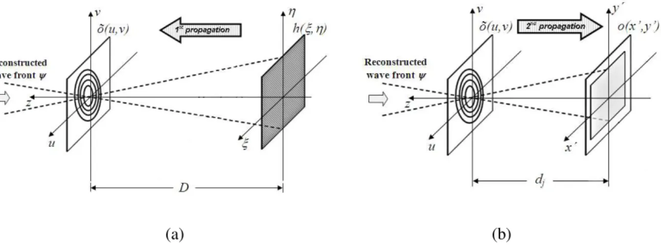
For digital reconstruction, we will use the Double Propagation Method [15] which consists in two
steps for wavefront reconstruction, the first propagation until the focal plane [12], Fig. 1(a), later on
the complex amplitude of the diffraction pattern in this plane is calculated and it is done a new
propagation process until the image plane Fig. 1(b).
This method allows performing the image reconstruction beginning from holograms focused in the
CCD plane or out of it and with only one hologram the phase field can be calculated with curvature
correction caused by microscopic objective. For the experimental application it is programmed in the
(a) (b)
Fig. 1. Double Propagation Method for image reconstruction, where (a) first propagation until the focal plan, and (b) new
propagation process until the image plane.
III. EXPERIMENTS
(a) (b)
Fig. 2. Experimental Setup for Photorefractive Digital Holographic Microscopy (PRDHM) with photorefractive sillenite Bi12TiO20 (BTO) crystal as recording medium, where M’s are mirrors, BS’s are beam-splitters, SF’s arespatial filter, L’s are lens, Po’s are polarisers, MO is a microscopic objective, PRC is a BTO crystal, SAMPLE is a transparent object and CCD is camera: (a) photorefractive holographic recording process in BTO crystal; and (b) holographic reading for digital
holographic reconstruction.
This Figure 2 displays experimental setup for PRDHM. The Fig. 2(a) shows the photorefractive
holographic recording process in BTO crystal by diffusive regimen, where, the
He-= 632.8nm) after passing through a beam-splitter BS1 is divided in reference 1, I0,R1(x,y), and object,
I0,O(x,y), beams, then these are expanded by SF’s and pass through a lens L’s to correct their
parallelism. An objective (50X, 0.95NA) directs the image into de BTO crystal which combines it
with the reference beam a 30 degree angle between them and gives the volume hologram recording of
optically reconstructed by diffraction of reference beam 1, I0,D(x,y), in holographic grating recorded in
BTO crystal (equation 3) and these one interfere with reference beam 2, I0,R2(x,y), producing an image
hologram
( , ) ( , )1 2 ( , ). ( , )1 cos
) ,
( ( / ) 2
, 0 2 , 0 2 ) / ( , 0 2 , 0 1 t D R t D
R x y I x y e I x y I x y e
I y x
I (4)
where, is the phase-shift of the holographic pattern, I1(x,y), which will be digitalized by CCD
camera (ImagingSource Inc) and by digital reconstruction the amplitude and phase image is finally
obtained. As it is know a slight angle is introduced between the object and the reference beams in the
second interferometer for off-axis holography. The camera uses an array of 1024 × 768 pixels with
pixel size of 4.65 μm and 24-bit scale output. An USB-2 cable connects the camera to the computer.
The image reconstruction is performed by the HOLODIG program supported in MatLab©[12], using
Double Propagation reconstruction algorithms [15].
IV. RESULTS
For testing the capture system it was used a glass slide resolution target as objet and an objective 50x
0.95, Fig. 3. First, the hologram of the object image is recorded in BTO crystal, in according with Fig.
2(a). In following, the diffracted beam in hologram grating that carried the holographic image
(amplitude and phase) and the reference beam 2 produce an image hologram which will be digitalized
by CCD camera (this hologram is displayed in Fig. 3(a)). This hologram erasure due the diffracted
beam delay. Finally, the images reconstruction (phase and amplitude) was done by mean of the DPM
method using one hologram. In Fig. 3(b-c) are displayed the reconstructed amplitude and phase
image, respectively, and Fig. 3(d) shows the 3D phase graphic of the number 10 of a glass slide
resolution target.
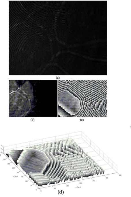
Additionally, we are applying the technique to a thin film in glass plate using objective 50x 0.95. In
Fig. 4(a) is displayed the hologram digitalized by CCD camera, Fig. 4(b) the reconstructed amplitude
image, Fig. 4(c) the reconstructed phase image, and Fig. 4(d) shows the 3D phase graphic. The results
Fig. 3. Results of the glass slide resolution target by PRDHM: (a) reading-reconstruction hologram, (b) intensity image, (c)
Fig. 4. Results of the thin film in glass plate by PRDHM: (a) hologram, (b) intensity image, (c) phase map, (d) phase 3D
representation.
V. CONCLUSIONS
In conclusion, we reported on a system for holographic microscopy that uses an integrated system
of the photorefractive and digital holography, so-called Photorefractive Digital Holographic
Microscopy. The system demonstrates, for the first time (to the best of our knowledge), through a
photorefractive holographic recording on a fast photorefractive BTO crystal and
reading-reconstruction hologram by digital holographic microscopy method is possible to obtain the
amplitude, phase and 3D imaging of the microstructures. The presented results and the uses of
photorefractive fast crystals at holographic recording medium indicated this system as potentials for a
dynamic holographic microscopy, where using multiplexing device as photorefractive holographic
recording and reading-reconstruction process can occur in different times.
ACKNOWLEDGMENT
The authors thank financial support from UFABC, CAPES, FAPESP (grant 2009/11429-2) and CNPQ (grant 309911/2011-7).
REFERENCES
[1] P. Gunter and J. P. Huinard, "Photorefractive effects and materials I," in Photorefractive Materials and Their Applications II, Vol. 62 of Topics in Applied Physics (Springer, Berlin, 1988).
[2] A. A. Kamshilin and M. P. Petrov, "Continuous reconstruction of holographic interferograms through anisotropic diffraction in photorefractive crystals," Opt. Commun. 53, 23–26 (1985).
[3] M. P. Georges and Ph. C. Lemaire, "Real-time holographic interferometry using sillenite photorefractive crystals. Study and optimization of a transportable set-up for quantified phase measurements on large objects," Appl. Phys. B 68, 1073-1083 (1999).
[4] M. R. R. Gesualdi, D. Soga, and M. Muramatsu, "Real-time holographic interferometry using photorefractive sillenite crystals with phase-stepping technique," Opt. Laser Eng . 44, 56-67 (2006).
[5] M. R. R. Gesualdi, E. A. Barbosa, and M. Muramatsu, "Advances in phase-stepping real-time holography using photorefractive sillenite crystals," J. Optoelectron. Adv. Mater. 8, 1574-1583 (2006).
[6] M. R. R. Gesualdi, M. Mori, M. Muramatsu, E. A. Liberti, and E. Munin, "Phase-shifting real-time holographic interferometry applied to load transmission evaluation in dried human skull," Appl. Opt. 46, 5419-5429 (2007) [7] P. P. Banerjje, G. Nehmetallah, N. Kukhtarev, S. C. Praharaj, Applied Optics, 47, 21, 3877 (2008).
[8] U. Schnars and W. Jüptner, "Digital recording and numerical reconstruction of holograms," Meas. Sci. Technol. 13, R85-R101 (2002).
[9] T. Zhang and I. Yamaguchi, "Three-dimensional microscopy with phase-shifting digital holography," Opt. Lett. 23, 1221-1223 (1998)
[10]E. Cuche, P. Marquet, and C. Depeursinge, "Simultaneous amplitude-contrast and quantitative phase-contrast microscopy by numerical reconstruction of Fresnel off-axis holograms," Appl. Opt. 38, 6994-7001 (1999)
[11]S. De Nicola, A. Finizio, G. Pierattini, D. Alfieri, S. Grilli, L. Sansone, and P. Ferraro, "Recovering correct phase information in multiwavelength digital holographic microscopy by compensation for chromatic aberrations," Opt. Lett. 30, 2706-2708 (2005)
[12]B. Kemper and G. von Bally, "Digital holographic microscopy for live cell applications and technical inspection," Appl. Opt. 47, A52-A61 (2008)
[13]Zhao Jian-Lin, Zhang Peng, Zhou Jian-Bo, Yang De-Ching, Yang Dong-Cheng, Li EnPu, “Visualizations of Light -induced Refractive Index Changes in Photorefractive Crystals Employing Digital Holography”, Chin.Phys. Lett, 20, 10, 1748 (2003).
[14]M. de Angelis, S. De Nicola, A. Finizio, G. Pierattini, P. Ferraro, S. Grilli, M. Paturzo, L. Sansone, D. Alfieri, and P. De Natale, "Two-dimensional mapping of electro-optic phase retardation in lithium niobate crystals by digital holography," Opt. Lett. 30, 1671-1673 (2005).