Abstract
Ant colony optimization (ACO) is a class of heuristic algorithms proposed to solve optimization problems. The idea was inspired by the behavior of real ants, related to their ability to find the shortest path between the nest and the food source. ACO has been applied successfully to different kinds of problems. So, this manuscript describes the development and application of an ACO algorithm to find the optimal stacking sequence of laminat-ed composite plates. The developlaminat-ed ACO algorithm was evaluat-ed on four examples for symmetric and balancevaluat-ed lay-up. The results of the first three cases, in which the classical lamination theory was used to obtain the structural response of rectangular plates, were compared to those obtained from the literature using genetic algorithms (GA) and other ACO algorithm. The fourth example investigates the maximization of fundamental frequen-cies of rectangular plates with central holes, where the structural response was obtained by finite element analysis, showing that this optimization technique may be successfully applied to a broad class of stacking sequence problems for laminated compo-sites.
Key words
laminated composite material; stacking sequence; ant colony optimization.
An ant colony algorithm applied to lay-up optimization
of laminated composite plates
1 INTRODUCTION
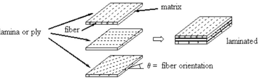
Laminated composite materials consist of stacks of layers, each layer usually composed by a matrix of polymeric material and fibers oriented in a specific direction. Figure 1 shows a scheme of a lami-nate composite material. Lamilami-nated composites give the designer the ability to tailor the material according to the application and the structures formed by these materials present high stiff-ness/mass and strength/mass ratios.
Rub em M atimoto Koid e,
Gustavo von Ze ska de França a nd Ma rco An tônio Lu erse n*
Laboratório de Mecânica Estrutural (LaMEs),
Universidade Tecnológica Federal do Paraná (UTFPR), Curitiba, Brazil
Received 23 Jan 2012
In revised form 09 May 2012
*
Figure 1 Laminated composite materials
The mechanical properties of composite laminates depend on the material of each layer, the number of layers, the thickness of each layer and the fiber orientations in each layer. The ply thick-nesses are often predetermined and the ply orientations are usually restricted to a small set of an-gles due to manufacturing constraints. This leads to problems of discrete or stacking-sequence opti-mization. As this optimization problem is very hard to solve, several techniques have been devel-oped. Genetic algorithms (GA) have been examined to solve these kinds of problems by different researchers in many studies [6, 9-13, 15]. Also, other techniques such as fractal branch and bound method were used by Terada et al. [14] and simulated annealing by Akbulut and Sonmez [2]. Re-cently, a new class of algorithms, the ant colony optimization (ACO), was developed to solve com-binatorial optimization problems. ACO was inspired by the observation of the behavior of real ants (Dorigo and Socha [4]). Regarding the ant colony optimization applied to laminated composites, Aymerich and Serra [3] presented the maximization of buckling load using ACO; in Abachizadeh and Tahani [1] a multi-objective optimal design for maximization of fundamental frequency and minimization of cost is studied and Wang et al. [16, 17] proposed a modified ant colony algorithm for stacking sequence optimization of rectangular laminate and composite stiffened panels for im-proving buckling strength.
This paper addresses the development of an ACO algorithm applied to the lay-up design of composites plates. Four examples are presented to show the performance of the developed algo-rithm. In the first one the fiber orientation (predefined ply angles) and the material (glass-epoxy or carbon-epoxy layer) are considered as design variables and the material cost is minimized under the constraints of buckling and a maximum weight. In the second example a critical load factor is max-imized under a constraint of a maximum of four contiguous plies with the same orientation. Only one material is used (graphite-epoxy layer), being the plies orientations the design variables. This contiguity constrain is to prevent matrix cracking [9, 10, 15]. In these two examples, rectangular plates are analyzed and the Classical Lamination Theory (see Jones [7]) is used to obtain the struc-tural response. The results of the optimized structures are compared to those obtained from other authors, using GA and ACO. In the third and fourth examples, the ply angles of squares plates with a central hole are optimized, aiming maximizing the fundamental frequency. Plates with dif-ferent diameters of the central hole are analyzed and the structural response is obtained through a commercial finite element code using Mindlin’s plate theory.
2 ANT COLONY OPTIM IZATION (ACO)
Ant colony optimization algorithm is a metaheuristic in which a colony of artificial ants cooper-ates in finding good solutions. This technique is applied to difficult discrete optimization prob-lems (Dorigo and Stülzle [5]). Based on the communication of real ants, called stigmergy, the simulation of artificial ants in ACO was developed. When the ants walk from-and-to a food source, they deposit in the ground a chemical substance called pheromone. The quantity of pher-omone on the grounds forms a pherpher-omone trails. Artificial ants may simulate pherpher-omone laying by modifying appropriate pheromone variables associated with problem states they visit while building solutions to the optimization problem (Dorigo and Socha [4]).
For the development of the ACO algorithm, graph G concepts are adopted (see Dorigo and Stülzle [5]). The artificial ants build solutions in stochastic constructive procedures until the con-nected graph G is complete (C, L), where C are the components and the all connections of com-ponents C is in the set L. In a procedure for building a graph, there are two elements associated in this algorithm step. The first one is the pheromone trail τ, associated with the components C
and the connections L. It influences in the artificial ants’ search process, and in the pheromone update by ants. The second is defined by a heuristic value η or heuristic information and is
re-lated to the problem information.
In this work, Ant Colony System (ACS) has been chosen as a tool for stacking sequence opti-mization. ACS is one of variation of ACO. This metaheuristic has a good performance to solve combinatorial optimization problems and has been successfully applied in many complex discrete problems. ACS algorithm has a framework based on three rules that manage the optimization problem. In this variant, the first procedure is the Tour Construction or pseudorandom propor-tional rule, defined by Dorigo and Stülzle [5] as
j =
arg max l∈ Νi
k τil ⎡
⎣ ⎤⎦ ⎡⎣ηil⎤⎦ β
{
}
, q ≤q0,J p
( )
ijk , q >q0,⎧
⎨ ⎪⎪ ⎪⎪
⎩ ⎪⎪ ⎪⎪
(1)
where q is a random variable uniformly distributed in [0, 1], q0 is a parameter for the best
pos-sible move (0≤q0≤1), k is an ant, β is a parameter which determines the relative influence of
the heuristic information, ηil is the heuristic information value, i, j are the initial and the next
choice or candidate, l is a candidate solution, N i
k is the feasible neighborhood of ant
k, J is a random variable obtained according to the probability distribution pijk (see Eq. (2)) in which the ant k chooses the next solution if q>q0. If q≤q0 it means that the ant is exploiting the learned
knowledge based on the pheromone trails and the heuristic information. If q>q0 the ant explores
pijk = τij ⎡ ⎣⎢ ⎤⎦⎥
α
ηij ⎡ ⎣⎢ ⎤⎦⎥
β
l∈ Νi k
∑
⎡⎣τil⎤⎦α⎡⎣ηil⎤⎦β, (2)
where α is a parameter which determines the relative influence of the pheromone trail.
The second rule is the Global Pheromone Trail Update, which is given by
τij ← (1−ρ)τ
ij +ρΔτij bs ,
∀(i,j)∈Tbs (3)
where ρ is the global pheromone evaporation rate (0<ρ≤1), Δτ ij
bs is the amount of pheromone
the ant k deposits on each best-so-far solution and Tbs is a set of the best connections. When this
rule is applied, both the evaporation and new pheromone deposit are update only to the best-so-far ant.
Local Pheromone Trail Update, the last rule, is applied during the tour construction. The phero-mone evaporation and a new pherophero-mone deposit are updated when an ant is exploiting or explor-ing the connection accordexplor-ing to the pseudorandom proportional rule, given by
τij ←(1−ξ)τij +ξ τ0 , (4)
where ξ is the local pheromone evaporation rate (0<ξ <1), and τ
0 is the initial pheromone
trails value.
The effect of the local updating rule, as explained in Dorigo and Stülzle [5], is that each time an ant uses an arc (i,j) or connection, its pheromone trails τ
ij is reduced and, therefore, the arc
becomes less attractive for the following ants.
3 ANT COLONY SYSTEM (ACS) APPLIED TO LAM INATED COM POSITES
The ACS algorithm must be set with some initial parameters, followed by the initial pheromone trail. Dorigo and Stülzle [5] suggest some parameter values for different kind of extensions of ACO. In this work the parameters are set following their recommendations. Table 1 shows the values used for each parameter.
Table 1 ACS parameters (present work)
Parameter m α β q0 ξ ρ
Value 5 1 2 0.9 0.1 0.1
As already mentioned, the ACO is based on the construction of a graph G(C, L) that the ants build the solutions following the state rule and the roulette wheel. The initial stacking sequence is chosen randomly and the pseudorandom rule is initialized following the Eq. (1). Aymerich and Serra [3] explain that a candidate solution is then constructed step-by-step by choosing probabil-istically the orientations of the stacks of the laminate. This tour construction is repeated applying the two sub-rules from Eq. (1) until the end of constructing the solution. Based on an ACO ap-plied to a travel salesman problem (TSP) benchmarking, Wang et al. [16, 17] presented the ACO modeled as a multi city-layer system. An ant in the city i chooses the next city j probabilistically in according to Eq. (1), building the stacking sequence optimization. The reduction of amount of pheromone minimizes the risk of stagnation in local optima and the new feasible combinatorial lay-up candidates can be explored. The Global Pheromone Trail Update process focuses on the best solution from the beginning of the stacking laminate sequence. For the laminate with best orientations, available by the objective function, the amount of pheromone is deposited for this specific ant trail. Abachizadeh and Tahani [1] related that this rule, which acts as positive feed-back, makes the search for the best solution more direct.
4 NUM ERICAL EXAM PLES
The developed ACO algorithm is tested on three cases shown below. All the parameters of ACO algorithm for these studies are in according to Table 1 and the laminates are symmetric and bal-anced.
4.1. Case 1- Hybrid laminated cost minimization with buckling and weight as constraints
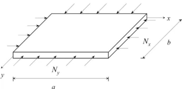
The problem addressed here consists in minimizing the cost of a simply support laminated com-posite rectangular plate, subjected to biaxial compressive loads (see Fig. 2). The laminate is symmetric and balanced and it can be made of two types of materials. The same problem was also solved by Girard [6] using a GA. The possibilities for the orientations of the plies are: 0°, +45°, -45° and 90°. The constraints are the maximum weight of 85 N and a minimum limit for the critical buckling factor (λ
min).
The materials are carbon/epoxy (CE) with cost of 8 monetary unit per kilogram (U/Kg) and glass/epoxy (GE) with 1 U/Kg. The characteristics and properties of those materials are present-ed in Table 2.
Table 2 Lamina’s material properties (case 1)
E1
(GPa)
E2
(GPa)
G12
(GPa) n12
Ply thick-ness e (mm)
Mass densi-ty
ρ (Kg/m3)
Carbon-Epoxy
(CE) 138.0 9.0 7.1 0.3 0.127 1605 Glass-Epoxy
(GE) 43.4 8.9 4.55 0.27 0.127 1993
This problem was solved for laminates with 48, 52 and 60 plies. The plate has length a = 0.9144 m and width b = 0.762 m. The ply thickness e is the same for all laminae. Gravity
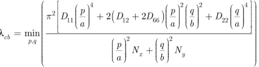
accel-eration is considered as 9.9 m/s2 as adopted by Girard [6]. The buckling load factor represents the critical buckling load divided by the applied load, and is given by (see Jones [7])
λ
cb =min p,q
π2 D 11 p a ⎛ ⎝ ⎜⎜ ⎜ ⎞ ⎠ ⎟⎟ ⎟⎟ 4
+2
(
D12+2D66)
p a ⎛ ⎝ ⎜⎜ ⎜ ⎞ ⎠ ⎟⎟ ⎟⎟ 2 q b ⎛ ⎝ ⎜⎜ ⎜ ⎞ ⎠ ⎟⎟ ⎟⎟ 2+D22 q a ⎛ ⎝ ⎜⎜ ⎜ ⎞ ⎠ ⎟⎟ ⎟⎟ 4 ⎡ ⎣ ⎢ ⎢ ⎢ ⎤ ⎦ ⎥ ⎥ ⎥ p a ⎛ ⎝ ⎜⎜ ⎜ ⎞ ⎠ ⎟⎟ ⎟⎟ 2
Nx + q
b ⎛ ⎝ ⎜⎜ ⎜ ⎞ ⎠ ⎟⎟ ⎟⎟ 2 Ny ⎛ ⎝ ⎜⎜ ⎜⎜ ⎜⎜ ⎜⎜ ⎜⎜ ⎜⎜ ⎜⎜ ⎞ ⎠ ⎟⎟ ⎟⎟ ⎟⎟ ⎟⎟ ⎟⎟ ⎟⎟ ⎟⎟ ⎟⎟ (5)
where Dij are the coefficients of the laminate bending stiffness matrix based on the classical
lami-nation theory (CLT), p and q determine the amount of half waves in the x and y-direction, re-spectively.
The values for minimum critical buckling factor (λ
min) and the biaxial compressive load
ap-plied to the laminates are shown in Table 3.
Table 3 Minimum values for critical buckling factor and compressive load
Numbers of plies Threshold buckling factor Load
NL λmin Nx(N/m) Ny(N/m)
48 150 175 175
52 250 175 175
60 375 175 175
Find:
{
θk,matk}
, θk ∈{
02,±45, 902}
,matk ={
CE, GE}
,k =1 to n Minimize: material costSubject to: λ
cb ≥λmin
W ≤W
max =85N
Symmetric and balanced laminated
(6)
where θk is the orientation and matkis the material of each stack of the laminate, and
n the total number of stacks. Each stack is composed of two layers with the same orientation but oppo-site signs (for instance, ±45o) to guarantee balance. Also, considering the symmetry of the lami-nate, n corresponds to the total number of layers divided by four (n = NL/4). λcb represents the
critical buckling factor and W is the weight of the laminate in Newtons (N). To respect the sym-metry condition, it is only operated with the half of the plies of the laminate, the other half being with the same angles. For the stacking sequence balance, the laminate is made considering always two contiguous laminae, in which the angles are the same but with opposite signs (for example, +45° and -45°, assigned for ±45). It notices that for the angles of 0° and 90°, its respective nega-tive pairs are equals, so its representation is 02 and 902, respectively.
The constraints on λ
cb and W are taken into account by penalization. The penalizations and
the evaluation function had been adapted from Girard [6] and are given by
F(x)=
f(x)− Δb gsum if gmin =0
f(x)+ Δp gmin if gmin ≠0
⎧ ⎨ ⎪⎪ ⎩ ⎪⎪
gmin =min 0;
(
g1( )
x ;g2( )
x)
gsum =g1
( )
x +g2( )
xg1
( )
x = λcbλ
min
−1+Δg
g2
( )
x =1−W( )
xWmax +Δg
Δb =0.000001 Δp =1
Δg = 0.01
(7)
where x represents the vector with the design variables, f(x) is the function to minimize, in this
case the cost, g1 is the constraint equation for λcb, g2 is the constraint equation for W, Δb is a
bonus factor, Δp is a penalization factor, Δg is a relaxation factor on constraints and F(x) the
penalized function. It is worthwhile to notice that the constraint violation, already considering the relaxation, occurs when g1 <0 and/or g2 <0. The condition gmin =0 corresponds that both
Table 4 shows the stacking sequence of the laminated plate obtained by Girard [6] using a GA and the comparative results obtained by the ACO of the present work. In the stacking sequences, the figures that are underlined correspond to the layers of glass-epoxy (GE), and the remaining figures to carbon-epoxy (CE). nf represents the average number of objective function evaluations needed to find the best solution and SD the correspondent standard deviation over 100 independ-ent runs.
Table 4 Comparative ACO (present work) versus GA (Girard [6])
NL λmin Method Stacking sequence
Material (CE/GE)
Cost (U)
Weight
(N) λcb nf(SD)*
48 150 GA [±453 / ±459]s 12/36 19.99 79.73 165.56 23945
52 250 GA [±456 / ±457]s 24/28 32.21 82.64 259.47 27345
60 375 GA [±4515]s 60/0 68.19 84.39 442.79 24984
48 150 ACO [±453 / 904 /
±457]s
12/36 19.98 79.73 190.23 23744
(1080)
52 250 ACO [902 / ±455 / 902
/ ±455 / 02]s
24/28 32.21 82.63 283.09 25581
(1225)
60 375 ACO [±4515]s 60/0 68.16 84.36 443.02 25039
(935)
* Girard [6] did not present the standard deviation of nf for the GA algorithm.
Analyzing the stacking sequences obtained by ACO and GA, both algorithms found the best configurations with carbon/epoxy plies on the external surfaces. These configurations satisfy the constraints of buckling, due to a higher bending stiffness and lower weight. Although the results for angle orientations present small difference between the two methods, the stacking sequence of materials and respective obtained costs reached similar results. For laminated plate with 60 lay-ers, the stacking sequence results found by ACO and by GA are identical. Considering laminates with 48 and 52 plies, the stacking sequence obtained by ACO did not find all orientations angles in ±45° and the critical buckling factor were also slightly higher than GA. The numbers of evalu-ations of the objective function were also similar for either methods, being slightly lower for the ant colony optimization in two situations (NL = 48 and NL = 52).
4.2. Case 2 – Critical load factor maximization
This problem was also investigated by Aymerich and Serra [3]. They applied an ant colony opti-mization metaheuristic to find the lay-up design of laminated plates aiming the maxiopti-mization of the critical load factor λ
c. The optimization problem can be defined as
Find: θk, θk ∈
02,±45, 902
{
}
, k=1 to n Maximize: λc = min(λcb,λcf)
Subject to: - Max. of 4 contiguous plies with the same orientation - Symmetric and balanced laminated
where λ
cb is the critical buckling load factor (see Eq. (5)), λcf is the critical failure factor based
on allowable strains (defined further), θk is the orientation of each stack and n is the total
num-ber of stacks. As presented in Eq. (8), the critical failure factor λ
c is the smallest between λcb
and λ cf.
The critical failure load factor λ
cf is defined as
λcf =min k min
ε1u
Sf ε1k , ε2u
Sf ε2k , γ12u
Sf γ12k ⎛
⎝ ⎜⎜ ⎜⎜ ⎜
⎞
⎠ ⎟⎟ ⎟⎟ ⎟⎟ ⎡
⎣ ⎢ ⎢ ⎢
⎤
⎦ ⎥ ⎥
⎥ (9)
where ε i u
, i=1,2 and γ12u
, are the ultimate strains; ε i k
, i=1,2 and γ12k are the strains in the
mate-rial principal directions of the kth lamina and Sf is the safety factor, set as 1.5.
The material properties of the layers are presented in Table 5.
Table 5 Graphite-epoxy lamina’s properties (case 2)
Elastic material properties Ultimate strains
E1 (GPa) E2 (GPa) G12 (GPa) υ 12 ε1
u
ε 2
u
γ12u
127.59 13.03 6.41 0.3 0.008 0.029 0.015
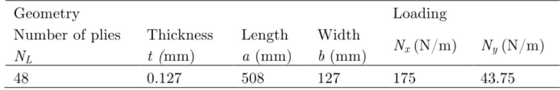
The characteristics of the plate analyzed in this case, which are composed only by graph-ite/epoxy material are exposed in Table 6. The Ny loading corresponds to 25% of Nx.
Table 7 shows the results obtained for this case, compared to the ones obtained by Aymerich and Serra [3]. Despite the fact that optimal stacking sequences are different from those obtained by Aymerich and Serra [3], the correspondent load factors λ
cb and λcf are quite close. The
differ-ences are less than 2.5%.
Table 6 Geometric characteristics and loading of the laminated plate (case 2)
Geometry Loading
Number of plies
NL
Thickness
t (mm)
Length
a (mm)
Width
Table 7 Comparison ACO (present work) versus ACO (Aymerich and Serra [3])*
Stacking Sequence Reference Load Factor
Buckling (λ
cb) Failure (λcf)
[±452/902/±453/02/±45/04/±45/02]s ACO (reference [3]) 12743.45 12678.78
[±45/902/±454/(02/±45/02)2]s ACO (reference [3]) 12725.26 12678.78
[902/±455/(02/±45/02)2]s ACO (reference [3]) 12674.85 12678.78
[±453/904/±452/02/±45/04]s ACO (present work) 12459.75 12690.69
[902/±454/(02/±45)3/02]s ACO (present work) 12418.12 12690.69
[±452/902/±452/02/±452/02/±45/04]s ACO (present work) 12634.43 12690.69
* problem based on Kogiso et al. [8] using GA search procedures.
4.3 Case 3 - M aximization of the Fundamental Frequency
The purpose of the problems presented in this section is to find the optimal stacking sequence to maximize the fundamental frequency of composite laminated plates made of graphite-epoxy. The optimization problem is formulated as
Find: θk, θk ∈ 0
2,±15,±30,±45,±60,±75, 902
{
}
, k=1 to nMaximize: ω (fundamental frequency)
Subject to: Symmetric and balanced laminate
(10)
Two kinds of structures are analyzed. First (case 3.1, subsection 4.3.1), rectangular plates with different ratios length/width are optimized. Second (case 3.2, subsection 4.3.2), square plates with a central hole of diameter D are analyzed, where different values for D are considered.
In case 3.1, during the optimization process, the structural response of the plates is obtained us-ing the Classical Lamination Theory (CLT). Next, the optimal lay-up design found is checked using a finite element method (FEM) code, aiming to validate the FEM results and the analytical responses. In case 3.2, the structural responses are computed using the FEM code.
4.3.1 Case 3.1 – Rectangular Plates
For rectangular plates, using the Classical Lamination Theory, the fundamental frequency is cal-culated by (Jones [7])
ωmn 2 = π 4 ρh D 11 m a ⎛ ⎝ ⎜⎜ ⎜ ⎞ ⎠ ⎟⎟ ⎟⎟ 4
+2 D
12+2D66
(
)
⎛ma⎝ ⎜⎜ ⎜ ⎞ ⎠ ⎟⎟ ⎟⎟ 2 n b ⎛ ⎝ ⎜⎜ ⎜ ⎞ ⎠ ⎟⎟ ⎟⎟ 2 +D 22 n b ⎛ ⎝ ⎜⎜ ⎜ ⎞ ⎠ ⎟⎟ ⎟⎟ 4 ⎡ ⎣ ⎢ ⎢ ⎢ ⎤ ⎦ ⎥ ⎥ ⎥ (11)
where ω
mn is the natural frequency of the vibration mode (m, n), h is the total thickness of the
ρ = 1
h ρ
(k) dz −h/2
h/2
∫
= 1NL ρ (k)
k=1
NL
∑
, (11)where ρ(k) is the mass density of the material in the k-th layer and NL is the total numbers of
plies of the laminate.
The geometric characteristics of the laminates are presented in Table 8. The ratio a/b varies from 0.2 to 2 with increment of 0.2. The material properties of graphite-epoxy layers (T300/5208) are reported in Table 9.
Table 8 Laminated plate characteristics
Number of plies Ply thickness Length/Width Width
NL e (m) a/b b (m)
8 2.5 x 10⁻⁴ 0.2 to 2.0 0.25
Table 9 Graphite-epoxy layer’s properties (cases 3.1 and 3.2)
Elastic material properties Mass density
E1 (GPa) E2 (GPa) G12 (GPa) u12 r (Kg/m3)
181 10.3 7.17 0.28 1600
The results obtained with the ACO algorithm developed in this work are presented in Table 10. This table also shows the results provided by Abachizadeh and Tahani [1] for the same case, also using ACO. The last two columns of the Table 10 show the value of the fundamental fre-quencies obtained by the finite element code for the optimal design and the percentage difference between the numerical and analytical results.
Table 10 Optimum stacking sequence for maximum fundamental frequency (case 3.1)
a/b
ACO - Abachizadeh and Tahani [1] ACO – Present Work Finite elements
Difference % Stacking sequence ω (rad/s) Stacking
sequence
ω
(rad/s) ω (rad/s)
0.2 [0]4s 24390 [0]4s 24389.88 24150.68 0.98
0.4 [0]4s 6170 [0]4s 6170.01 6138.48 0.51
0.6 [±15]2s 2801 [±15]2s 2801.00 2772.14 1.03
0.8 [±30]2s 1797 [±30]2s 1797.21 1745.66 2.87
1.0 [±45]2s 1413 [±45]2s 1413.00 1362.76 3.56
1.2 [±45]2s 1189 [±45]2s 1189.11 1148.69 3.4
1.4 [±60]2s 1078 [±60]2s 1077.86 1051.49 2.45
1.6 [±75]2s 1016 [±75]2s 1016.42 1007.89 0.84
1.8 [90]4s 1003 [90]4s 1002.46 1001.29 0.12
4.3.2 Case 3.2 – Square Plates with Central Hole
Consider a composite square plate with side dimensions of 0.25 m and a central hole of diameter
D, as shown in Fig. 3. The diameter varies between 0.0 to 0.16 m by an increment of 0.04 m. The parameters are identical to those of previous simulations. Table 11 shows the results for this problem. Optimal solution matched ± 45° for all layers as expected due to symmetry of the prob-lem and geometry, therefore the results are consistent. nf represents the average number of
ob-jective function evaluations that the algorithm needed to find the best solution and SD the corre-spondent standard deviation. Figure 4 presents the first vibration mode for a plate with diameter
D= 0.04.
Figure 3 Square plate with a central hole
Table 11 Optimal results obtained for case 3.2
D(m) Stacking sequence w (rad/s)
f
n (SD) 0.00 [±45]2s 1362.76 13.3 (1.0)
0.04 [±45]2s 1350.26 12.3 (1.0)
0.08 [±45]2s 1409.70 9.0 (0.8)
0.12 [±45]2s 1632.75 10.5 (0.6)
0.16 [±45]2s 2138.23 14.8 (0.5)
5 CONCLUSIONS
In this paper, the Ant Colony Optimization (ACO) was applied to the optimization of laminated composite plates. The formal representation that the artificial ants use in a problem formulation for ACO was applied to the analysis of laminated composite plates. Many numerical simulations were carried out and three cases are selected to evaluate the performance of metaheuristic proce-dures. The tests were divided in two parts. First, the developed ACO algorithm was compared with other optimization techniques. Finally, free vibration analyses were carried out using ACO and a FEM code to solve laminated composites with complex geometry. Based on this formula-tion, the ACO was implemented to minimize the cost or maximize the buckling load factor, con-sidering the constraints. ACO was also applied to rectangular and squared composite plates to obtain their highest fundamental frequencies, which were used as reference data. The stacking sequence was obtained from ACO and simulated in a commercial finite element code. Subsequent-ly, the ACO algorithm, developed in Matlab, was coupled with a FEM code. FinalSubsequent-ly, composite square plates with central holes were simulated, and the results agreed with those expected for this geometry. Based on these numerical cases, the ACO has been successfully applied in the lay-up composite laminate plate optimization and the proposed connection approach provides an efficient tool to optimize complex laminated composite structures.
Acknowledgements The authors are thankful to the Brazilian funding agencies CAPES and
CNPq for providing finance assistance to carry out this research.
References
[1] M. Abachizadeh and M. Tahani. An ant colony optimization approach to multi-objective optimal design of symmetric hybrid laminates for maximum fundamental frequency and minimum cost. Structural and Multi-disciplinary Optimization, 37:367-376, 2009.
[2] M. Akbulut and F.O. Sonmez. Optimum design of composite laminates for minimum thickness. Computers & Structures, 86:1974-1982, 2008.
[3] F. Aymerich and M. Serra. Optimization of laminate stacking sequence for maximum buckling load using the ant colony optimization (ACO) metaheuristic. Composites: Part A, 39:262-272, 2008.
[4] M. Dorigo and K. Socha. An introduction to ant colony optimization. IRIDIA – Technical Report No. TR/IRIDIA/2006/010, Université Libre de Bruxelles, 2007.
[5] M. Dorigo and T. Stützle. Ant colony optimization. Cambridge: MIT, 2004.
[6] F. Girard. Optimisation de stratifiés en utilisant un algorithme génétique. M.Sc. dissertation. Faculté des Sciences et de Génie, Université Laval, Québec, Canada, 2006 (in French).
[7] R. M. Jones. Mechanics of Composite Materials. Scripta Book Company, Washington, 1975.
[8] N. Kogiso, L.T. Watson, Z. Gürdal and R. Haftka. Genetic algorithms with local improvement for composite laminate design. Structural and Multidisciplinary Optimization; 7:207-218, 1994.
[9] R. Le Riche and R. Haftka. Optimization of Laminate Stacking Sequence for Buckling Load Maximization by Genetic Algorithm. AIAA Journal, 31:951-956, 1993.
[10] R. Le Riche and R. Haftka. Improved genetic algorithm for minimum thickness composite laminate design.
Composites Engineering, 5:143-161, 1995.
[13] R.H. Lopez, M.A. Luersen and J.E.S. Cursi. Optimization of Hybrid Laminated Composites using a Genetic Algorithm. Journal of the Brazilian Society of Mechanical Sciences and Engineering, 32:269-278, 2009. [14] Y. Terada, A. Todoroki and Y. Shimamura. Stacking sequence optimizations using fractal branch and bound
method for laminated composites. JSME International Journal, Series A, 44:490-498, 2001.
[15] A. Todoroki and R. Haftka. Stacking sequence optimization by a genetic algorithm with a new recessive gene like repair strategy. Composites: Part B, 29:277-285, 1998.
[16] W. Wang, S. Guo, N. Chang, Z. Feng and W. Yang. A modified ant colony algorithm for the stacking se-quence optimization of a rectangular laminate. Structural and Multidisciplinary Optimization, 41: 711-720, 2010.
![Table 4 Comparative ACO (present work) versus GA (Girard [6])](https://thumb-eu.123doks.com/thumbv2/123dok_br/18884824.423570/8.892.128.783.258.487/table-comparative-aco-present-work-versus-ga-girard.webp)
![Table 7 Comparison ACO (present work) versus ACO (Aymerich and Serra [3])*](https://thumb-eu.123doks.com/thumbv2/123dok_br/18884824.423570/10.892.129.806.118.346/table-comparison-aco-present-work-versus-aymerich-serra.webp)


