Abstract— Nonlinear effects has been appointed as the main limitation in coherent optical fiber transmission. Digital Back-Propagation algorithms and Maximum Likelihood Sequence Estimation are two of the current studied methods to cope with such impairment and extend the systems maximum reach. In this article, we analyzed both methods in a 112 Gb/s Dual Polarization Quadrature Phase Shifting Keying (DP-QPSK) optical coherent system through simulations and experimental results. In order to reduce the huge required computational complexity, a modified back-propagation algorithm is also analyzed.
Index Terms—Digital signal processing, Dual Polarization, Nonlinear Effects Compensation, Optical Coherent Systems, PDM-QPSK
I. INTRODUCTION
Optical systems play key roles in telecommunications networks today, especially in intercontinental
long-haul systems, where optical amplification and wavelength division multiplexing provide the
lower cost per transmitted bit at very high data rates. However, as all kinds of communication
networks, long-haul optical systems has been pushed to the limit of its current capacity due the
growing data traffic from broadband internet applications, as well as the increasing number of
connected devices. To cope with this crescent demand, without face the high costs involved in expand
the optical network, it is necessary to better explore the installed fibers capacity employing
modulation formats with higher spectral efficiency. The vast majority of optical systems today use the
binary On-Off Keying (OOK), which gives a spectral efficiency of only 0.5 b/s/Hz [1]. Most current
research in high capacity optical systems consider a multilevel modulation format, such as Quadrature
Phase Shift Keying (QPSK), combined with polarization multiplexing, a technique that allows
sending different information in each orthogonal polarization in a single mode fiber, thus doubles the
system capacity. Polarization Division Multiplexing QPSK (PDM-QPSK), proposed as a standard
format for 112 Gb/s transponders [2], has a spectral efficiency of 2 b/s/Hz.
However, the use of such advanced modulation formats implies in deep changes in optical systems,
particularly in the receiver structure. Although it is possible to perform polarization demultiplexing in
optical domain, and receive the DQPSK format with differential direct detection receivers, there is
substantial performance improvement by employing coherent detection and Digital Signal Processing
Nonlinear Effects Compensation in Optical
Coherent PDM-QPSK Systems
Eduardo S. Rosa1* ,Victor E. S. Parahyba1, Júlio C. M. Diniz1, Vitor B. Ribeiro1 and Júlio C. R. F. Oliveira1
(DSP). In the most common approach, the coherent receiver uses an intradyne topology, similar to a
homodyne topology, but with no phase synchronization between the transmitted carrier and local
oscillator. The resulting phase error is corrected in digital domain by a feed forward carrier recovery
algorithm. DSP can also perform polarization demultiplexing in digital domain with a dynamic
equalizer, tracking the rotations of the State of Polarization (SoP) during fiber propagation caused by
random changes in fiber birefringence. The same algorithm can mitigate the intersymbol interference
induced by Polarization Mode Dispersion (PMD), optical and electrical filtering and other static or
slow time varying linear distortions. While the effect of Chromatic Dispersion (CD) can be too
intense to be compensated in a dynamic equalizer, it can be done by a static parametric equalizer, both
in time or frequency domain, offering advantages in performance, management and power
consumption over optical dispersion compensation using Dispersion Compensating Fibers (DCF) or
Dispersion Compensating Modules (DCM).
With the mentioned techniques, it is possible to overcome most of linear impairments present in
optical communication systems [3]. Further improvement in maximum reach and system performance
can be achieved with the mitigation of fiber propagation nonlinear effects. As nonlinear effects are
strongly dependent of the optical power during propagation, a usual method to avoid it is to keep low
signal power during transmission, and then considering a linear propagation model. However, limiting
the signal power also limits the maximum achievable Optical Signal-to-Noise Ratio (OSNR),
penalizing system performance. Much effort has been done to equalize nonlinear effects to allow the
operation at high signal powers. Among the proposed methods, one that received great attention is the
Digital Back-Propagation (DBP) [4][5].
DBP consists in extend the static equalized used to compensate CD to include the deterministic
nonlinear effects. This method can be very effective to equalize intra-channel nonlinear interactions
such Self Phase Modulation (SPM), Intra-channel Cross Phase Modulation (IXPM) and Intra-channel
Four Wave Mixing (IFWM). However, the computational complexity of back-propagation becomes
too high for practical implementation, leading to intensive research to develop more efficient DBP
algorithms [6][7][8].
Another approach to mitigate fiber nonlinearities is the application of the Maximum Likelihood
Sequence Estimation (MLSE) method. The idea of the Maximum Likelihood Sequence Estimation is
to utilize conditional probability density functions (pdf) to describe the signal as a conditional
sequence, and not as separate symbols. Training is required to compute the channel statistics and to
estimate the channels conditional pdfs. After that we use a maximum likelihood criterion to estimate
the sequence of received symbols.
In this work we analyzed two different back-propagation algorithms aimed to equalize a 112G/s
PDM-QSPK signal in nonlinear regime and we make a comparison with the MLSE method. Through
DBP algorithm. Section III is devoted to describe the back-propagation algorithms. In Section IV we
describe the MLSE method implemented in this work. Section V includes simulation and experiment
setups and results and finally section VI summarizes the main conclusions and address possible future
works in this field.
II. OPTICAL SYSTEM MODEL
The deterministic effects in a single mode fiber include attenuation, chromatic dispersion and
signal-to-signal nonlinear interactions. Considering single channel propagation, those effects are
usually described by a pair of coupled Nonlinear Schrödinger Equations (NLSE), one for each
orthogonal polarization, in a so called Manakov system [9]:
| | | | (1)
where is the electric field of a signal propagating in a given polarization, is the electric
field of a signal propagating in an orthogonal polarization, is the loss coefficient and describes fiber
attenuation, and are related to CD and is the nonlinear parameter.
Considering only the terms related to and in (1), this equation solutionleads to a linear system
modeling only CD contribution, described in the frequency domain by:
[ ( )] (2)
In practice, CD is commonly measured by the dispersion parameter and dispersion slope ,
related to and by:
(3)
( ) (4)
where is the carrier wavelength and is the speed of light. In many optical systems, especially those
which employ Standard Single Mode Fibers (SSMF), the dispersion parameter is much higher than
dispersion slope, and then slope impact is neglected.
The last term of (1) describes the intra-channel nonlinear interactions related to Kerr effects; the
dependence of refraction index in a dielectric medium with the electrical field intensity of such
medium is submitted. In the fiber case, this change depends on the signal power, given by
| | | | . Considering only this term in (1), the output electrical field is given by:
| | | | (5)
instantaneous signal's amplitude, as oppose to the linear rotation in frequency domain caused by CD,
which depends only on fiber parameters , and z. This effect is referred to as Self Phase
Modulation, and exhibits a complex interaction with CD, causing both phase and amplitude
distortions in the signal. As already mentioned a common measure to avoid nonlinearities is to keep
low launch powers and then consider a linear propagation model. However, it limits the maximum
OSNR and therefore the system performance at large distances. Indeed, launch power follow a
tradeoff between nonlinear effects and OSNR limitation, which leads to an optimal value refereed as
Nonlinear Threshold (NLT). NLT varies widely with fiber parameters and modulation formats.
As NLSE includes only deterministic effects, it does not include Polarization Mode Dispersion
(PMD), a linear non-deterministic time varying impairment related to fiber birefringence. PMD
induces pulse broadening with average value given by:
√ (6)
where is the PMD coefficient and is the fiber length. The instantaneous PMD impact depends on
the State of Polarization (SoP), which is also time varying.
Receiver noises, such thermal and shot noise, are usually neglected in long haul systems, since
Amplified Spontaneous Emission (ASE) noise from optical amplifiers became dominant. ASE noise
also can induce phase changes due nonlinear effects in a similar way that SPM, a phenomenon called
Nonlinear Phase Noise (NPN).Coherent systems can also suffer with phase noise due phase
fluctuations in both transmitter and local oscillator lasers.
III. DIGITAL BACK-PROPAGATION
In general, signal processing at the receiver includes front-end correction, static equalization, timing
recovery, dynamic equalization and carrier recovery [3]. In most cases, static equalization includes
only CD, using a linear equalizer given by equation (2). However, to achieve even higher data rates
and further distances it is necessary to overcome the nonlinear effects imposed by the optical fiber. As
a result, nonlinearity mitigation using DSP became a major research topic.
Many different approaches have been evaluated to cope with nonlinear effects in optical systems,
including constellation design [10], nonlinear adaptive equalizers [11], transmitter pre-distortion [12],
MLSE [13]and optical or electronic phase conjugation [14]. However, the most studied method for
coherent systems is the Back-propagation algorithm, which involves consider the nonlinear term of
NLSE to design a digital static equalizer at the receiver, compensating SPM and CD at the same time.
In a similar way used for linear CD compensation, this equalizer is found by solving equation (1) using α, , and γ from optical link, but with opposite signs. Unfortunately, NLSE do not have a closed analytical solution, but can be numerically solved using a non-interactive asymmetric
Split-Step Fourier Method (SSFM). To do so, we have to split equation (1) in a linear and a nonlinear
(7)
| | | | (8)
Instead of solving the entire NLSE, we solve the linear term, given by (7), and then the nonlinear
term, given by (8). This procedure can only be applied if the impact of linear distortion does not affect
nonlinear operation and vice-versa, which stands only for short fiber sections. As a result, we have to
split the optical link into sections with length small enough to apply (7) and (8) separately, and
solve all sections in sequence. Linear component solution is already given in frequency domain by
(2). In this solution we neglected the attenuation term, since signals power has been normalized after
sampling. The solution for the nonlinear component over is given in time domain by:
(9)
| | | | (10)
where is the effective length, given by:
(11)
The equalizer structure consists in repeated steps of linear and nonlinear operations. As linear
equalization is performed in frequency domain, while nonlinear equalization is performed in time
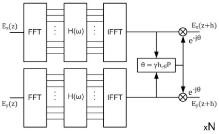
domain, each step includes FFT and IFFT operations. Figure 1 shows a schematic of the BP
equalizer.
Figure 1. Step of back-propagation algorithm with linear equalization in frequency domain and nonlinear equalization in time domain.
DBP computational complexity scales linearly with the number of steps, reaching unrealistic values
for current practical applications [6][7][8]. On the other hand, we cannot reduce the number of steps
taken as a complexity lower bound.
In [8], a modified Correlated Back Propagation (CBP) was proposed, including the contribution of
the first order IXPM to nonlinear equalization by considering the neighbor symbols:
∑ | | | |
(12)
where is the number of symbols considered and is a weighting coefficient. Although that
algorithm has a slightly higher complexity per step, it requires fewer steps to achieve the same
equalization accuracy, and then the overall complexity is reduced.
IV. MAXIMUM LIKELIHOOD SEQUENCE ESTIMATION
The MLSE estimation process employs the Viterbi algorithm which is implemented by establishing
possible states, where is the number of signal constellation points and refers to the memory
length. Each transition between states is related with one of the pdfs of the channel. There are several
ways to estimate the signal's pdf in order to perform the Viterbi Algorithm at MLSE. In general it is
quite common to consider the received pdf to be approximately Gaussian [15]. Thus, the
determination of the signal's pdf becomes simply the mean and variance estimation of this Gaussian.
In this work, instead of Gaussian approximation, the training sequence was used to build the
histogram of the received signal, since that approach is more accurate. The received samples are
quantized with a resolution of 4 bits for the real part and 4 bits for the imaginary part, producing a 2-D
histogram with 16x16 possible bins for each possible state transition. The number of occurrences in
each bin is counted and an estimate is made for each pdf, considering each transition. This procedure
requires a state model with basis M = 16 for the complete characterization of the PDM-QPSK signal,
demanding an enormous computational effort. However it is possible to reduce the complexity, by
considering the two polarization signals separately (M = 4). In this work it was considered a 3-symbol
memory system (n = 3), which gives 64 states for each polarization. A direct consequence of this
approach is that it would not be possible to fully compensate Intra-Channel Cross Phase Modulation
(IXPM), but it is a good compromise between performance and implementation complexity.
V. SIMULATION AND EXPERIMENTAL RESULTS
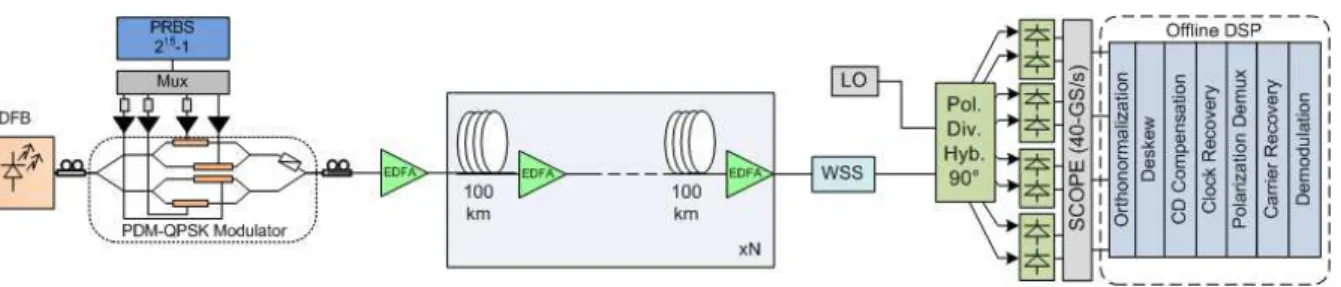
We perform a set of simulations to evaluate linear equalization, Back-Propagation algorithms and
MLSE. Transmission was simulated in Optiwave™, where the signal is automatically up-sampled to
32 samples per symbol to properly account for nonlinear effects.The simulated transmitter, optical
Figure 2. 112 G/s PDM-QPSKSimulation Setup
The transmitter consists of a DFB laser centered at 193.4 THz with 500 kHz linewidth, followed by
PDM-QPSK modulator driven by four 28 Gb/s binary inputs. The transmitted sequences are a 230
pseudo random pattern.
The link consists of a varying number of spans composed by 100 km of standard single mode fiber
(SSMF) and an erbium doped fiber amplifier (EDFA) with noise figure of 5 dB and 20 dB optical
gain to fully compensate the span attenuation. The fiber has attenuation ( ) of 0.2 dB/km, dispersion
(D) of 16.75 ps/nm/km, and a nonlinearity coefficient ( of 1.5 W/km; for simplicity, we do not
consider third-order dispersion effects (slope). Self phasemodulation nonlinear effects were included
according to the Schrödinger equation and polarization mode dispersion effects are considered with a
PMD coefficient of 0.1 √ ⁄ .
After fiber transmission, the received signal was pre-amplified (constant power of 0 dBm), filtered
using a 200 GHz bandwidth 4th order Gaussian optical band-pass filter, and passed through a PBS.
Each polarization component was then coherently detected by an electro-optical receiver with
2º phase shift error and two pairs of balanced photodiodes. The local oscillator DFB laser has a
linewidth of 500 kHz and a frequency offset of 2 GHz from the transmitter laser frequency. The four
electric analogical signals are filtered using a 22 GHz bandwidth 1st order low pass gaussian filter to
simulate the effect associated with a real receiver and by a 30 GHz bandwidth 4th order low pass
gaussian filter to simulate the filtering effect of an oscilloscope. Finally, the data is re-sampled to 2
samples per symbol.
Digital post-processing is performed entirely in MATLAB™ and includes an algorithm set described in [16]. We employ a GSOP orthonormalization algorithm to compensate front-end
imperfections and Gardner algorithm to timing and clock recovery. Dynamic equalizer is updated
with conventional CMA. Frequency offset estimation employs a frequency domain approach and
finally a Viterbi-Viterbi algorithm performs phase estimation and correction. Static equalization,
applied after orthonormalization procedure, uses a conventional FDE for linear equalization, or the
presented back-propagation algorithms for joint compensation of nonlinear effects and CD.
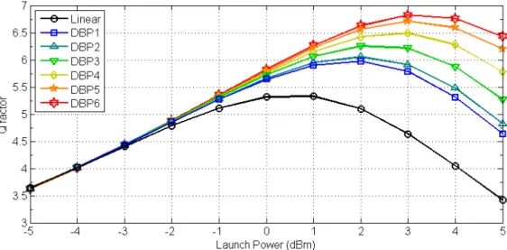
Figure 3 shows a comparison between the achieved Q-factor using only linear equalization, DBP
with one to six steps per span (DBP1 to DBP6) for launch power from -5 to +5 dBm. In that
Figure 3. 112 G/s PDM-QPSKSimulation Setup
One can see that all algorithms have similar performance for power lower than -2 dBm, since
nonlinear effects in such low power are too weak to impact Q-factor and additive noise became the
dominant impairment. As the launch power increases, DBP outperforms linear equalization,
achieving higher NLT and maximum Q-factor. For linear equalizer the maximum Q-factor is 5.4 at
+1 dBm launch power. DBP1 achieves factor 6 at +2 dBm launch power, while DBP6 achieves
Q-factor 6.5 at + 3 dBm.
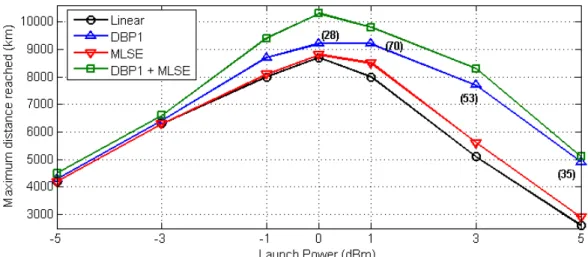
Figure 4 shows the comparison between the linear equalization, DBP1, MLSE and MLSE + DBP1,
in terms of maximum achievable distance. That distance is defined as the maximum distance in which
the BER stills bellow than . In this simulation, MLSE gives only a marginal improvement
over linear equalization, reaching 8800 km instead of 8700 km. DPB1 alone achieve 9200km, about
5% more than linear equalization. MLSE and DBP combined give the better results, reaching
10300km, a improvement about 18%. This gain alone does not justify the enormous computational
effort required by DBP algorithm and MLSE.
Figure 4 also shows the number of stages for which we managed to reduce by using the CBP
algorithm. At the launch power of 1 dBm CBP uses 70 steps instead of 92 steps employed by
common DBP, keeping the same bit error rate after 9200 km. The reduction of computational
complexity using CBP was approximately 30%. As might be expected, it is more difficult to reduce
the complexity at higher launch powers because of increasing nonlinear effects impact. In our
implementation of the CBP algorithm, we fixed equal to seven and equal to 0.02 for all launch
powers and symbol delays. Further increasing in the number of considered symbols did not improve
Figure 4. Comparison of the maximum distance achieved using each algorithm
We conducted further investigation with an experimental WDM setup depicted in figure 5. The
transmitter consists of 32 lasers from channel C21 to C60, modulated in a 112Gb/s PDM-QPSK
format. All but C41 are DFB lasers with 2 MHz linewidth. C41 is a tunable External Cavity Laser
(ECL) with 100 kHz linewidth. Each laser has an independent polarization controller. Two
independent pattern generators and PDM-QPSK modulators are used, one for C41 and other for DFB
lasers. Modulators output are joined by power combiners and the resulting signal is amplified by an
EDFA to achieve a launch power of 0 dBm per channel. The recirculation loop is composed by four
pure silica fiber spans with 50 km, and one with 26 km. Fiber attenuation is 0.176 dB/km in C band,
CD coefficient is 18.6 ps/nm.km, fiber effective area is 80 µm2 and PMD coefficient is below 0.067 ps/√km. Between each span there is an EDFA with maximum 10 dBm maximum output power and 4.6 dB maximum noise figure. The receiver comprises a pre-amplifier (EDFA) followed by a
200 GHz tunable optical filter responsible for filtering the noise introduced by the optical amplifier
and a 90º hybrid, responsible for the demodulation of the optical PDM-QPSK signal. The signal is
sampled by an Oscilloscope at samples per second, enabling the application of digital signal
Figure 5. 112 G/s PDM-QPSKSimulation Setup
Figure 6 shows the comparison of BER (calculated from Q-factor) varying with distance when we
apply linear equalization, DBP1, MLSE and MLSE + DBP1. For shorter distances, MLSE gives the
smallest gain, followed by DBP1. MLSE combined with DBP1 leads to a very small improvement
over DBP alone. As distance grows, all methods but linear equalization seems to converge to the same
performance, slightly better than linear equalization. It is well known that for WDM systems the
impact of XPM is considerably higher than SPM [17]. There are generalizations of the DBP algorithm
including the influence of other channels, and then accounting for XPM. However, the computational
complexity of these algorithms are much higher than the classic DBP for single channel and
furthermore, it is necessary to know the information received byall channels which is impractical.
Figure 6. Comparison of BER varying with distance for an experimental transmission of 32 WDM channels
Although the nonlinear equalization algorithms do not appear interesting for PDM-QPSK
transmission, it is very promising for higher modulation formats such as PDM-16QAM and beyond
provided by DBP in both modulation formats, using the previous simulation setup. The reach
extension provided by DBP1 is much higher in 16QAM than in QPSK, and can be observed even in
launch power below -1dBm. In addition, PDM-16QAM systems are limited to shorter distances due to
OSNR requirements, which also limits the number of steps required in back-propagation and
computational complexity, making nonlinear compensation for such modulation format more
cost-effective.
Figure 7. Comparison of the distance improvement by using the DBP algorithm at differents lanch powers
VI. CONCLUSION
The DBP algorithm achieved only a 500 km improvement over linear equalization, at a cost of huge
computational complexity. The application of the MLSE method for nonlinear mitigation showed a
considerably smaller gain than DBP, as expected, but the combination of both methods presented a
reasonable gain in relation of DBP1, achieving 1600 km, an 18 % improvement over linear
equalization. The experimental results show that in dense WDM systems, the gain provided by DBP
or MLSE are even reduced by XPM contribution.
For DBP, when we increase the number of steps per span, the NLT gets progressively higher, but
the computational complexity also gets higher. Much effort has been made in making the DBP
algorithm computationally more advantageous; however, as evidenced by calculations shown, the
algorithm remains impractical for real applications in the context of PDM-QPSK transmissions over
SSMF fibers. CBP complexity is by 30% lower than DBP for 9200km at 1dBm, but stills too high for
the small gain obtained.
Nevertheless, the growing need for spectral efficiency requires even higher modulation formats
such as PDM-16QAM and beyond. For these modulation formats, the compensation of nonlinear
effects seems vital to achieve significant distances and the utilization of the DBP algorithm becomes
ACKNOWLEDGMENT
To FUNTTEL and CPqD for funding and support.
REFERENCES
[1] P. Winzer, R.-J. Essiambre, " Advanced optical modulation formats.", Proceedings of the IEEE, May 2006 [2] “100G Ultra Long Haul DWDM Framework Document,” Optical Internetworking Forum (OIF) , july 2009.
[3] S. Savory, "Digital Coherent Optical Receivers: Algorithms and Subsystems", Journal of Selected Topics in Quantum
Electronics, August 2010
[4] X. Li, X. Chen, G. Goldfarb, E. Mateo et al, "Electronic post-compensation of WDM transmission impairments using coherent detection and digital signal processing", Optic Express, January 2008
[5] E. Ip, and J. M. Kahn, "Compensation of dispersion and nonlinear impairments using digital backpropagation", Journal of
Lightwave Technology, October 2008.
[6] D. Rafique, M. Mussolin, M. Forzati et al, "Compensation of intra-channel nonlinear fibre impairments using simplified back-propagation algorithm", Optic Express, May 2011
[7] L. B. Du and A. J. Lowery, “Improved single channel backpropagation for intra-channel fiber nonlinearity compensation in
long-haul optical communication systems,” Optic Express, August 2010
[8] L. Li; Z. Tao; L. Dou; W. Yan; S. Oda; T. Tanimura; T. Hoshida and J. C. Rasmussen, "Implementation efficient nonlinear equalizer based on correlated digital backpropagation", Optical Fiber Communication Conference, 2011
[9] G. P. Agrawal, Nonlinear Fiber Optics, (Academic Press, 2007)
[10] J. Zhang and I. B. Djordjevic, "Optimum signal constellation design for rotationally symmetric optical channel with coherent detection", Optical Fiber Communication Conference, 2011
[11] F. P. Guiomar; J. D. Reis; A. L. Teixeira and A. N. Pinto, "Mitigation of intra-channel nonlinearities using a frequency-domain volterra series equalizer", European Conference on Optical Communication, 2011
[12] L. Dou; Z. Tao; L. Li; W. Yan; T. Tanimura; T. Hoshida and J. C. Rasmussen, "A low complexity pre-distortion method for intra-channel nonlinearity", OFC, 2011
[13] N. Stojanovic; Y. Huang; F. N. Hauske; Y. Fang; M. Chen; C. Xie and Q. Xiong, "MLSE-based nonlinearity mitigation for WDM 112 Gbit/s PDM-QPSK transmissions with digital coherent receiver", Optical Fiber Communication Conference, 2011 [14] E. F. Mateo ; X. Zhou and G. Li, "Electronic phase conjugation for nonlinearity compensation in fiber communication systems",
Optical Fiber Communication Conference, 2011
[15] M. S. Alfiadet al., “Maximum-Likelihood Sequence Estimation for Optical Phase-Shift Keyed Modulation Formats,” Journal of Lightwave Technoloy, vol. 27, 4583-4594 (2009).
[16] V. B. Ribeiro; J. C. M. Diniz; V. E. S. Parahyba; E. S. Rosa; S. M. Ranzini; F. A. Silva; J. C. R. F. Oliveira, "Processamento de sinais para redes ópticas coerentes digitais de alta velocidade", Cadernos CPqD tecnologia, july-december, 2011