Abstract
Relative humidity of environment affects creep and shrinkage behaviour of a concrete member of composite tall buildings. These buildings are more prone to redistribution of forces as adjacent steel columns and RCC shear walls have quite different characteristics.
In this paper, study is carried out to evaluate the effect of relative humidity of environment for a composite building using analytical prediction model, CEB-FIP updated 1999 as the facility of short term testing may not be always available and thus, prediction of creep and shrinkage of concrete at any time by extrapolation is not possible. An accurate procedure, Consistent Procedure, CP available in literature is modified by incorporating analytical prediction model CEB-FIP updated 1999.
It has been shown that differential deflections in a composite frame shear wall system are significantly affected by relative humidity. It has been further reported that although, the steel columns have only elastic deformation for the chosen composite frame systems, there is significant increase in design forces when relative humidity decreases.
Key words
Creep, shrinkage, composite buildings, shear walls, differential deflections, relative humidity
Effect of relative humidity on creep-shrinkage
behav-iour of composite tall buildings
1 INTRODUCTION
Creep and shrinkage of concrete have a pervasive cause of excessive deflections and damages in concrete structures. In a tall building, the time-dependent differential vertical shortening between adjacent vertical members due to creep and shrinkage of concrete may be sufficiently large to cause distress in nonstructural elements and to induce significantly structural actions in the horizontal elements (especially in the upper region of the building). These differential vertical shortenings aris-es as adjacent vertical members have different characteristics such as percentage of reinforcement, volume to surface ratio and stress level caused due to different gravity loadings or from non-uniform
P eey us h C ho wdh ary 1 Rav i K. Sh arm a *, 2
1Assistant professor, M.B.M. Engineering
College, J.N.V. University, Jodhpur, India
2Associate professor, C.T.A.E., Maharana
Pratap University of Agriculture and Technology, Udaipur, India
Received 13 Apr 2012 In revised form 21 Nov 2012
Latin American Journal of Solids and Structures 10(2013) 571 – 584
Notations
AP approximate procedure
δ un-restrained total deformation,
Ib , Ic moment of inertia of beam and column respectively;
Ac cross sectional area of column;
Isw,Asw moment of inertia and cross sectional area of shear-wall
res-pectively;
CP consistent procedure;
Rsw , psw volume to surface ratio and reinforcement percentage of shear
wall respectively
RH relative humidity of the environment;
d
k e,
δ
d
k e( )
vertical elastic deflections and elastic differential respectively,d
k t
,
δ
d
kt
( )
vertical deflections, total and total differential respectivelyP
ke
,
P
kt
axial forces, elastic and total respectively.
Superscript
e elastic;
t total;
Subscript
k typical story/floor
Latin American Journal of Solids and Structures 10(2013) 571 – 584 stresses caused by lateral force. These differential shortenings are of cumulative nature along the height and therefore, have importance with increasing height of the buildings.
Maru et al. (2001) developed a procedure termed as Consistent Procedure, CP for both low and high stiffness of beams of the buildings. In this procedure the shortcomings of earlier procedures available in the literature (Fintel et al. 1987), have been removed. In this procedure stress transfer from concrete to steel are evaluated using Rate of Creep Method. This procedure has been further modified using the more accurate stress transfer method, Age-Adjusted Effective Modulus Method AEMM (Sharma 2002) for concrete and composite buildings.
Sharma and Choudhary (2007) presented a numerical study to evaluate the effect of beam stiffness on the creep and shrinkage behaviour in composite frame shear wall systems using Con-sistent Procedure, CP. It is shown that considerable load redistribution occurs between the RCC shear wall and the steel columns and additional moments occur in beams.
Chowdhary and Sharma (2009) reported detailed numerical study to evaluate the effect of shear wall properties on deflection and load transfer among adjacent vertical members in a composite frame shear wall system using CP.
Sharma and Nagpal (2008) presented a procedure for creep and shrinkage analysis of buildings with low beam stiffness. This procedure is designated as Approximate Procedure, AP.
Chowdhary and Sharma (2011) carried out a comparison of CP and AP procedures to determine the error in the Procedure AP to evaluate the creep and shrinkage effects in composite buildings. It has been shown that the error to determine axial forces from AP is small for composite frame shear wall systems with very low beam stiffness. It was further reported that AP is erroneous at low beam stiffness and high beam stiffness and thus, it was suggested that CP should be used for higher beam stiffnesses.
In the above reported studies of composite buildings, the creep and shrinkage of concrete at any time is obtained by extrapolating the short term test results conducted on the concrete specimens under controlled conditions in the laboratories.
Creep and shrinkage of concrete is affected by number of factors. These factors are divided into intrinsic factors and extrinsic factors. Relative humidity of the environment is an extrinsic factor and affects creep and shrinkage behaviour of a concrete member. The creep and shrinkage deformation of a concrete member must be multiplied a suitable factor if relative humidity is more than 40% (Fintel et al. 1987).
Chaudhary et al. (2008) have recognised that relative humidity has significant effect on time dependent changes in deflections and bending moments in a composite frame and should be considered properly.
Vafai et al. (2009) have evaluated creep and shrinkage effects for concrete tall building and it has been shown that relative humidity has significant effect on creep and shrinkage strains in a 25 story building. The percentage of change of column shortening in a story is more than fifty percent in a 25 story concrete frame –shear wall building.
Latin American Journal of Solids and Structures 10(2013) 571 – 584
No systematic study is available on the effect of relative humidity on creep and shrinkage behaviour of composite tall buildings. Systematic study is carried out in this work using an analytical prediction model as the facility of short term testing may not be always available and thus, the prediction of creep and shrinkage of concrete at any time by extrapolating is not possible. The most commonly used analytical prediction models are ACI 209R (1992), B3 (Bazant and Baweja 1995) and CEB-FIP (1970, 1978, 1993) models. Estimates of creep and shrinkage obtained by various models vary widely. Takacs (2002) compared CEB-FIP model and B3 models for analysis of a bridge and found the former to be in better agreement with the measurements.
Howells et al. (2005) have reported that no individual model can be said to be the most accurate and for selection of a model, the relative importance of the various input parameters used in the model and sensisitivity of the prediction models to the important parameters must be known. Rela-tive humidity of environment and compressive strength of concrete have been identified to be the most influential parameters in governing the creep and shrinkage strains (Howells et al. 2005). Fur-ther, CEB-FIP and B3 models have been found to be more sensitive to the changes in these influen-tial parameters than ACI 209R model.
Bazant and Li (2008) have shown that CEB-FIP updated 1999 model is better than ACI 209R model. Also, Ghodousi et al. (2009) presented an experimental study to compare various prediction models and recommended that CEB-FIP updated 1999 model (FIB 1999) is simple and easy to apply.
In this paper, studies are carried out to evaluate the effect of relative humidity of the environment for a composite building using analytical prediction model, CEB-FIP updated 1999 (FIB 1999). In this prediction model CEB-FIP updated 1999, the creep coefficient and shrinkage strain at any time is evaluated by considering material properties at any time and properties of structural member using formulations available in the literature (FIB 1999). Consistent Procedure, CP (Sharma 2002) is modified by incorporating these formulations to evaluate the creep coefficient and shrinkage strain at any time to carry out the systematic study.
2 CONSISTENT PROCEDURE, CP (Sharma 2002)
In a composite building (Figure 1), RCC shear walls have both elastic and inelastic deformations. In a segment of a RCC shear wall, total unrestrained inelastic deformation δ consists of creep
deformation and shrinkage deformation. These creep and shrinkage deformation are evaluated using stress transfer method, Age-Adjusted Effective Modulus Method, AEMM (Sharma 2002).
Latin American Journal of Solids and Structures 10(2013) 571 – 584 In the segment of a RCC shear wall, total unrestrained inelastic deformation δ is restrained by
beams of a composite building and this action of the beams results into the restraining end forces in the segment of a RCC shear wall. The restraining end forces are evaluated for applied dead and live loads. The occurrence of the application of dead and live loads in a composite building is different. Thus, the analysis incorporating creep and shrinkage effect for two loads is carried out in two parts as dead load analysis and combined dead and live loads analysis.
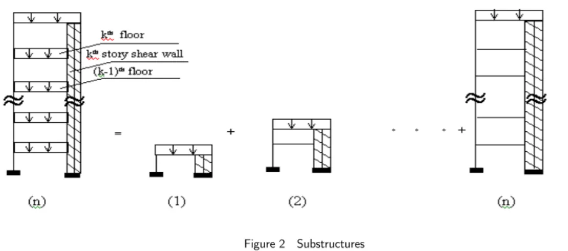
In the dead load analysis, sequential nature of dead load is considered and linear analysis of n-substructures having number of stories varying from 1 to n (Figure 2) is performed. Frame analysis is carried out by considering the actual time of occurrence of the all elastic and inelastic forces for the evaluation of inelastic deformations (creep and shrinkage). Total member forces and vertical deflections are obtained for the each substructure.
Figure 2 Substructures
In the combined dead and live loads analysis, the part of live load (which is of permanent nature) is applied to the complete frame - shear wall system (n stories)( Figure 2) and frame analysis is carried out. The time duration (≈ 20 years) after the application of live load is divided in number of intervals. For each time interval, deformations are evaluated corresponding to the calculated column axial forces up to this time interval. Total member forces and total deflections at the end of the time interval are evaluated for each time interval.
3 PREDICTION MODEL, CEB-FIP
CEB-FIP model (1970, 1978 and 1993) is an empirical method in which creep coefficient is divided into reversible delayed elastic components and irreversible flow components. These components are evaluated from the equations, in which relative humidity and cross sectional area of the member are important parameters. These parameters are also used to evaluate the shrinkage coefficient from the recommended equations in the model. This model is referred as CEB-FIP 1990 model.
Latin American Journal of Solids and Structures 10(2013) 571 – 584
coefficient in this model is also modified and is divided into autogenous shrinkage and drying shrinkage components. These components are evaluated from the recommended equations in the model. This model is referred as CEB-FIP updated 1999 model (FIB 1999).
4 NUMERICAL STUDY
Composite frame - shear wall system (Figure 3) consisting of RCC shear wall and steel column, has been chosen to carry out systematic study as this frame-shear wall system is more prone to redistri-bution of forces since adjacent steel columns and RCC shear walls have quite different characteris-tics. The steel columns will have only elastic deformations whereas RCC shear walls will have both, elastic and inelastic deformations due to creep and shrinkage of concrete.
Three composite frame-shear wall systems are selected to carry out the numerical study. The composite frame-shear wall system 1 comprises of 3 bays and 30 stories with each bay of span 5.0 m, story height 3.0 m (Figure 3). The study has been carried out assuming column properties (column size) to be constant for all the stories. This assumption is made so that effect of relative humidity alone can be evaluated. External columns are of steel (moment of inertia, Ic = 0.002684 m4, area,
Ac= 0.05858 m2) and interior RCC shear walls are of size 3.0 x 0.6 m (moment of inertia, Isw =
0.162 m4, area, Asw= 1.8 m2 and volume to surface ratio, Rsw = 22.5 cm). Percentage of
reinforce-ment in shear walls, psw is taken as 0.45%. All beams are of steel having moment of inertia, Ib =
Ic/50.
The other composite frame-shear wall systems 2 and 3 are having 45 and 60 number of storeys respectively. The properties of the members of these frame shear-wall systems are the same as of composite frame-shear wall system 1.
Latin American Journal of Solids and Structures 10(2013) 571 – 584 5 EFFECT OF VARIATION IN RELATIVE HUMIDITY
The effect of relative humidity has been studied by taking relative humidity of the environment, RH as 50%, 75% and 98%. All frame-shear wall systems are subjected to uniform dead loading of 35.0 kN/m and uniform live loading of 10.0 kN/m. The total time to consider creep and shrinkage effects is taken as 20 years. This time duration in combined dead and live loads analysis, is divided into 20 intervals. The concrete mix is of grade M60 and the normal hardening cement has been chosen for the study.
Final differential vertical deflections, elastic
δ
( )
d
ke andδ
( )
d
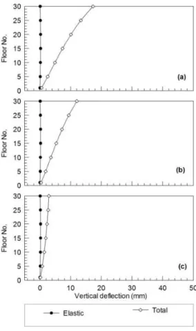
kt between RCC shear walls andsteel columns (difference in deflections of shear walls and columns) are shown in Figures 4, 5 and 6 for composite frame system 1, 2, 3 respectively. It is observed that change between differential elas-tic deflections
δ
( )
d
ke and differential total deflectionsδ
( )
d
kt increases with the decrease in relativehumidity. The concrete creep and shrinkage increases with the decrease in relative humidity and thus, the high creep and shrinkage effects are observed at low relative humidity.
Latin American Journal of Solids and Structures 10(2013) 571 – 584
Figure 5 Comparison of differential vertical deflections between steel columns and RCC shear walls for system 2: (a) RH=50%; (b) RH=75%; (c) RH=98%
Latin American Journal of Solids and Structures 10(2013) 571 – 584 It is also observed from figures 4, 5 and 6 that change in differential elastic deflections
δ
( )
d
keand differential total deflections
δ
( )
d
kt increases with the increase of number of storeys fromNS=30 to NS=60. The change in differential elastic deflections
δ
( )
d
ke and differential totaldeflec-tions
δ
( )
d
kt for NS=30 (RH=98%) is 2.83 mm whereas the corresponding change for NS=60(RH= 50%) is 18.67 mm.
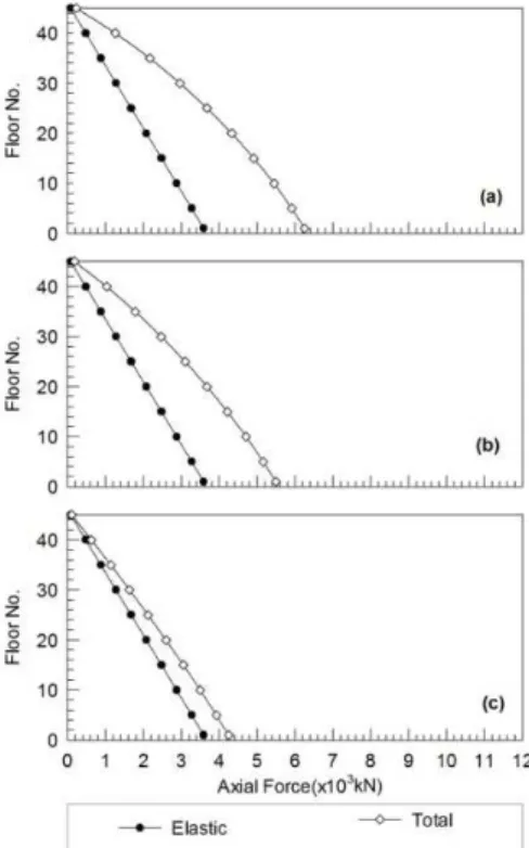
Figures 7, 8 and 9 show variations in final axial forces in steel columns,
P
ke
and
P
kt
for compo-site frame systems 1, 2, 3 respectively. Although, steel columns have only elastic deformations but it may be seen that
P
k t
in steel columns increases due to load transfer from RCC shear walls. The steel columns and RCC shear walls are having monolithic connection by steel beams and load redis-tribution takes place between shear walls and adjacent steel columns. This load transfer results from higher
d
k e
and
d
k t
in RCC shear walls than those in steel columns.
Figure 7 Comparison of axial forces in steel columns for system 1: (a) RH=50%; (b) RH=75%; (c) RH=98%
It is also observed from Figures 7, 8 and 9 that the change between
P
ke andP
kt increases as therelative humidity decreases. The increase between
δ
( )
d
ke andδ
( )
d
kt (Figures 4, 5 and 6) occursLatin American Journal of Solids and Structures 10(2013) 571 – 584 between
P
k e
and
P
kt
for NS = 30 (RH = 98%) is 22.0 kN whereas the corresponding maximum change for NS = 60 (RH = 50%) is 145.0 kN.
Figure 8 Comparison of axial forces in steel columns for system 2: (a) RH=50%; (b) RH=75%; (c) RH=98%
Latin American Journal of Solids and Structures 10(2013) 571 – 584 The percentage change in elastic
P
k e
in the steel columns and RCC shear walls along the height are shown in Table 1 at three levels (at top, middle and bottom) for relative humidity = 50%. It may be noted that the percentage change in elastic axial forces increases along the height for NS = 30, 45 and 60 and the percentage change in elastic axial forces is maximum at the top level for NS=60.
Table 1 Percentage change in axial force in steel columns and RCC shear walls at RH = 50%
S. No. No. of storeys
Axial force % change in Axial force
Steel columns(kN) RCC Shear walls(kN)
1 30
Level Elastic Total Level Elastic Total Columns Shear walls Bottom 2381.0 4254.6 Bottom 6868.2 6151.8 78.69 -10.43
Middle 1271.5 2751.6 Middle 3669.2 3115.6 116.41 -15.09
Top 78.5 211.9 Top 227.9 182.0 169.81 -20.11
2 45
Bottom 3583.3 6249.6 Bottom 11604.2 8937.8 74.41 -22.98
Middle 1673.7 3675.9 Middle 5413.8 3411.6 119.62 -36.98
Top 78.6 222.9 Top 258.9 114.6 183.60 -55.74
3 60
Bottom 4782.4 7942.5 Bottom 15467.5 12307.3 66.08 -20.43
Middle 2474.8 5033.4 Middle 7987.7 5429.1 103.39 -32.03
Top 78.6 223.6 Top 258.9 113.9 184.47 -56.02
The percentage change in elastic axial force in the steel columns and RCC shear walls along the height also are shown in Tables 2 and 3 for relative humidity = 75% and = 98% respectively.
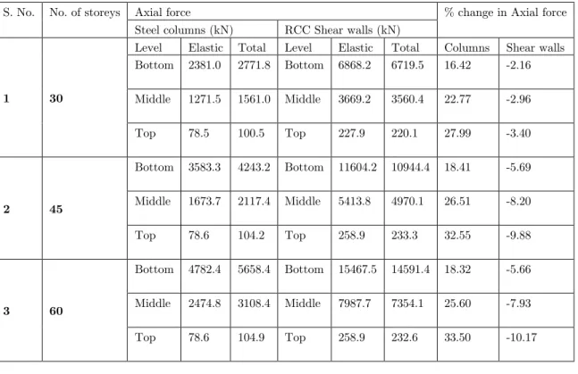
It can be observed from Tables 1, 2 and 3 that the percentage change in axial forces for steel columns and RCC shear-walls are greatest at the top level for the variation of relative humidity from 50% to 98%. The high percentage change in the top portion is not of design significance since magnitude of these axial forces is small.
At bottom and mid level, the percentage changes in
P
ke
for relative humidity = 50%, (fck = 60
MPa, and NS=60) in
P
ke
Latin American Journal of Solids and Structures 10(2013) 571 – 584
Table 2 Percentage change in axial force in steel columns and RCC shear walls at RH = 75%
S. No. No. of storeys Axial force % change in Axial force
Steel columns (kN) RCC Shear walls (kN)
1 30
Level Elastic Total Level Elastic Total Columns Shear walls Bottom 2381.0 3703.5 Bottom 6868.2 6357.7 55.55 -7.43
Middle 1271.5 2312.1 Middle 3669.2 3276.5 81.85 -10.70
Top 78.5 171.2 Top 227.9 195.7 117.93 -14.11
2 45
Bottom 3583.3 5489.6 Bottom 11604.2 9697.9 53.20 -16.43
Middle 1673.7 3095.3 Middle 5413.8 3992.2 84.94 -26.26
Top 78.6 179.4 Top 258.9 158.1 128.22 -38.93
3 60
Bottom 4782.4 7055.9 Bottom 15467.5 13194.1 47.54 -14.70
Middle 2474.8 4304.6 Middle 7987.7 6157.9 73.94 -22.91
Top 78.6 180.1 Top 258.9 157.4 129.08 -39.20
Table 3 Percentage change in axial force in steel columns and RCC shear walls at RH = 98%
S. No. No. of storeys Axial force % change in Axial force
Steel columns (kN) RCC Shear walls (kN)
1 30
Level Elastic Total Level Elastic Total Columns Shear walls Bottom 2381.0 2771.8 Bottom 6868.2 6719.5 16.42 -2.16
Middle 1271.5 1561.0 Middle 3669.2 3560.4 22.77 -2.96
Top 78.5 100.5 Top 227.9 220.1 27.99 -3.40
2 45
Bottom 3583.3 4243.2 Bottom 11604.2 10944.4 18.41 -5.69
Middle 1673.7 2117.4 Middle 5413.8 4970.1 26.51 -8.20
Top 78.6 104.2 Top 258.9 233.3 32.55 -9.88
3 60
Bottom 4782.4 5658.4 Bottom 15467.5 14591.4 18.32 -5.66
Middle 2474.8 3108.4 Middle 7987.7 7354.1 25.60 -7.93
Latin American Journal of Solids and Structures 10(2013) 571 – 584 6 CONCLUSIONS
(a)The nature of load transfer among vertical members depends upon differential deflections. The differential deflections are significantly affected by relative humidity. The change between elastic differential deflections and total differential deflection increases with the decrease in relative hu-midity.
(b)When relative humidity decreased, significant load transfer from the RCC shear walls to the steel columns takes place. In the composite frame-shear wall systems considered, it is observed that the percentage change between
P
ke andP
kt is significant when the relative humidity of theenvironment is reduced from 98% to 50%.
(c)Although, the steel columns have only elastic deformation for the chosen composite frame systems, there is significant increase in design forces when relative humidity varies. The design of steel columns is thus, critical and proper considerations must be taken in the design of these members.
References
[1] ACI Committee 209 (1992). “Prediction of creep, shrinkage and temperature in concrete structures”. American Concrete Institute, Detroit.
[2] Adam, I., and Taha, M. M. R. (2011), "Identifying the significance of factors affecting creep of concrete: A probabilistic analysis of RILEM database”, International Journal of ConcreteStructures and Materials, 05(2), 97-111.
[3] Bazant, Z. P., and Baweja, S. (1995), in collaboration with RILEM Committee TC 107-GCS, "Creep and shrinkage prediction model for analysis and design of concrete structures—model B3" (RILEM Recommendation). Materials and Structures, 28, 357–365.
[4] Bazant, Z. P., and Li, G. (2008), "Unbiased statistical comparison of creep and shrinkage prediction models”. A.C.I. Material Journal, 105(6),610–621.
[5] Chaudhary S, Pendharkar U. and Nagpal, A.K (2008) “Service load behaviour of low rise composite frames considering creep, shrinkage and cracking”. Latin American Journal of Solids and Structures, 05, 237-258. [6] Chowdhary P.and Sharma, R.K (2009) “Creep - shrinkage behaviour of composite systems due to varying
shear wall properties”. Journal of Engineering and Applied Sciences, 04(2), 38-45.
[7] Chowdhary, P. and Sharma, R.K., (2011) “Evaluation of creep and shrinkage effects in composite tall buildings”. Journal “The Structural Design of Tall and special Building’s, 20(7), 871-880.
[8] Comite Europeen du Beton-Federation Internationale de la Precontrainte (CEB-FIP) (1970). International recommendations for the design and construction of concrete structures. Cement and Concrete Association, London.
[9] Comite´ Euro International du Beton-Fe´de´ration International de la Pre´contrainte, (CEB-FIP). (1978). Model code for concrete structures. 3rd Ed., Comite´ Euro International du Beton, Paris.
[10] Comite´ Euro International du Beton-Fe´de´ration International de la Pre´contrainte, (CEB-FIP). (1993). Model code for concrete structures. Thomas Telford, London
Latin American Journal of Solids and Structures 10(2013) 571 – 584
[12] Fintel, M., Ghosh, S. K., and Iyengar, H. S. (1987). “Column shortening in tall buildings - Prediction and com-pensation.” Publ. EB108 D, Portland Cement Association, Skokie, III., 1-34.
[13] Ghodousi P., Afshar M.H., Ketabchi H. and Rasa E. (2009), “Study of Early age Creep & Shrinkage of Con-crete Containing Iranian Pozzolans: An experimental Comparative Study”, Transaction of Civil Engineering, Sharif University of Technology, Vol. 16, pp 126-137.
[14] Howells, R. W., Lark, R. J., and Barr, B. I. J. (2005). “A sensitivity study of parameters used in shrinkage and creep prediction models.” Mag. Conc. Res., 57(10), 589-602.
[15] Maru, S., Asfaw, M. and Nagpal, A.K.(2001). “A Consistent procedure for creep and shrinkage effects in R.C. frames” Journal of Struct. Engrg., ASCE, 127(27), 726-732.
[16] Sharma, R.K.,(2002).” Behaviour of R.C. and Composite Tall Buildings due to Creep and Shrinkage,” PhD thesis, IIT Delhi, India.
[17] Sharma, R.K and Chowdhary P. (2007) “Creep and Shrinkage behaviour of Composite Frame shear wall systems under varying Beam Stiffness”, Proceedings of National Conference on Recent Trends in Geotechnical and Structural Engineering at MNIT Jaipur.
[18] Sharma, R.K. and Nagpal, A.K.(2008). “A procedure for creep and shrinkage analysis of frames with low beam stiffness” The Structural Design of Tall and Special Buildings, 17(4), 739-755.
[19] Takacs, P. F. (2002). “Deformations in concrete cantilever bridges: observations and theoretical modeling.” PhD thesis, Norwegian Univ. Sci. Tech., Trondheim, Norway.