Abstract— Frequency-shift-free all-optical amplitude regenerators based on fiber-four-wave mixing were investigated by means of simulations. These regenerators, comprised of two stages of highly nonlinear dispersion-shifted fiber, were designed using a heuristic procedure that implements a routine based on a genetic algorithm to optimize the device performance. A bit error rate improvement of up to four orders of magnitude was found as compared to a previous design approach discussed in the literature. It was due to a proper choice of the pump signal frequency regarding to the input signal that brings about a trade-off between four-wave mixing optical reshaping and four-wave mixing crosstalk leading to optimal optical regeneration. The proposed design method might be applied to other parametric devices that rely on four-wave mixing.
Index Terms— optical regeneration, four-wave mixing, heuristic procedure, crosstalk.
I. INTRODUCTION
Optical signals propagating along metropolitan area networks (MAN) may be significantly
impaired by the accumulating effects of chromatic dispersion, fiber nonlinearities, and amplified
spontaneous emission (ASE). Consequently, they will need to be regenerated, for example, during
transmission or before interconnecting with other networks. MANs, because of their typical reaches
and even for economic reasons [1], still benefit from using non-returning-to-zero on-off keying
(NRZ-OOK) modulation format. Furthermore, researchers have been looking for all-optical regeneration
strategies that are transparent to the bit rate. Notably, schemes that use nonlinear effects in dielectric
media have attracted much attention [1-9], especially four-wave mixing (FWM) fiber-based
regenerators [4-9]. Recently [7], it was experimentally demonstrated a FWM regenerator that
exhibited significant amplitude and phase noise suppression for returning-to-zero differential shift
keying (RZ-DPSK) signals. A parametric regenerator for 43 Gb/s returning-to-zero on-off-keying
(RZ-OOK) signals, tunable over a 20 nm range, was implemented using a highly nonlinear dispersion
shifted fiber (HNL-DSF) [8]. It has also been shown that a setup using FWM phase-sensitive
amplifiers (PSA) can regenerate PSK signals [9]. Recently, a two FWM-stage pump modulated
regenerator that preserves the input signal carrier frequency was investigated [10]. In the work
Design of Four-Wave Mixing
Frequency-Shift-Free Amplitude Regenerators
E. A. M. Fagotto, U. R. C. de Miranda,
School of Electrical Engineering, PUC-Campinas, Rod. D. Pedro I- km 136, Campinas, SP, 13086-900, Brazil [email protected], [email protected]
C. M. T. Tobar
discussed in this article, and to the best of our knowledge, for the first time, we present an efficient
approach to design pump-modulated fiber-FWM 2R regenerators for NRZ-OOK signals. This
approach employs a routine that implements a genetic algorithm (GA) [11] that optimizes the device
performance by exploiting a trade-off between FWM optical regeneration and FWM crosstalk. This
design approach has not been yet reported in the literature and it is shown to be advantageous as
compared to one discussed in [3]. The device stages were considered to be implemented with
HNL-DSFs. Finally, we observe a frequency-shift-free regenerator would prevent any network management
concern regarding transmission channel reallocation, since the device maintains the input signal
carrier.
II. FUNDAMENTALS OF 2RALL-OPTICAL REGENERATION
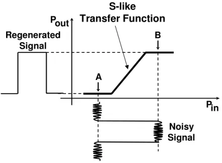
A. S-like Transfer Function
All-optical reshaping and reamplification (2R All-Optical Regeneration) of NRZ-OOK signals rely
on the implementation of an S-like optical power transfer function (Fig. 1) in a device (regenerator).
As far as the input signal noise amplitude does not exceed the lower (A) or higher (B) transfer
function steps, the regenerator will output a reshaped version of the original signal. Many different
approaches have been tried out to implement an S-like optical power transfer function (hereafter
referred to as S-like transfer function) and the most promising ones employed FWM in dielectric
media. FWM is a nonlinear effect that depends on the third-order of the electrical susceptibility [12].
In the next subsection, it will be reviewed how FWM can be used to achieve an S-like optical power
transfer function in HNL-DSFs.
S-like
Transfer Function
Regenerated
Signal
Pout
Pin
Noisy
Signal
A
B
B. FWM and the S-like transfer function
Two waves co-propagating, at frequencies 1 and 2, along an optical fiber, interact via FWM due to the medium nonlinearities and give rise to sidebands at frequencies + and − [12]:
1 2 2 1 2 − = −
+ (1)
By inspecting the well-known approximate solutions that describe the optical power at these
sidebands, one can gain an insight regarding how FWM can be used to implement an S-like transfer
function in optical fibers. For this purpose, consider the equation [13]:
(
)
(
)
2 1
2 2
2 1−
− = + α α α
ηγ (2)
where, 1, 2, and +correspond, respectively, to the optical powers at frequencies, 1, 2, and
+ at the output of a fiber of length . Furthermore,
α
is the attenuation coefficient,γ
is thenonlinear coefficient andη the FWM efficiency that is written as:
(
)
(
)
(
)
[
− −]
∆ − + ∆ + = 2 0 2 0 2 2 1 2 4 1 α α α αη (3)
(
−)
−(
−)
+ ∆ = ∆ α α γ 2 1 2 10
0 (4)
= 1−
(
−α)
(5)and 2 1 2 0 2 0 0 3 0 1 1 1 1
2 − −
≈
∆ π (6)
when 1 tends to zero, +will also tend to zero. Moreover, if 1 is high enough and ∆ 0 = π (is an odd number), +will be practically constant, corresponding to FWM saturation. Therefore,
from this simple discussion, it is possible understand, even if in a qualitative way, how FWM can be
used to implement an S-like transfer function. Finally, although (2) is written for +, a similar
argumentation will hold for the signal power at − .
III. FREQUENCY-SHIFT-FREE FWM-REGENERATOR
A single stage fiber-FWM regenerator is schematically depicted in Fig 2(a). A continuous wave
1, transmitted at frequency 1 and the signal to be regenerated, propagating at frequency 1,
are co-polarized and coupled into a HNL-DSF spool, where they co-propagate whilst FWM takes
place. The noisy signal needs to be previously amplified before being coupled into the fiber to serve
as a modulated pump. At the fiber output, first-order FWM products (or sidebands) will be found at
frequencies [12]:
1 1 1
1
1
1− = −
+ , (7)
a result directly derived from (1).
Albeit the frequency-shift described by (7) may be an interesting feature, it is not difficult to figure
out that sometimes it may also be an inconvenient one. For example, in a WDM system, there might
be situations when the network management would be prevented from using the device because,
otherwise, the regenerated copy frequency would fall on an already allocated transmission channel.
This sort of problem can be overcome if a second stage is added to provide a further frequency-shift
that will bring the regenerated copy back to the input signal carrier frequency. Figure 2(b) shows the
correspondent two-stage setup, where
2and 2− are, respectively, the second stage continuous
wave frequency and the lower frequency first-order FWM-sideband. This scheme, besides avoiding
the input signal carrier frequency-shift, also provides enhanced optical regeneration, since the signal is
regenerated twice. As it can be easily checked,
1 1
2 =4 −3 (8)
to prevent the regenerated copy carrier frequency-shift. In spite of (7) is a simple equation, a general
description of the power levels at
1
+ and −1requires numerically solving the nonlinear Schrödinger
IV. REGENERATOR DESIGN
Fiber-FWM stages considered in this work have a parameters set comprised by , , ,
, and (with
=
1, 2 indexing the first or the second stage) that stand, respectively, for theEDFA gain, continuous wave power, continuous wave frequency, input signal power and frequency.
Fiber parameters , 0 , 0 ,
α
, andγ
are, respectively, the fiber length, zero-dispersion frequency, dispersion slope, attenuation and nonlinear coefficients. In order to describe the FWMinterference for the general case, in a HNL-DSF stage, it is necessary to solve the nonlinear
Schrödinger equation (NLSE) [12]. Albeit there are simpler formalisms [12], [13] than the NLSE to
accomplish this goal, they will not hold, for example, when signal depletion is significant, which is a
potentially important situation for FWM optical regeneration as it will be shown in this work. To
solve the NLSE, we approached the problem using a software tool that implements the split-step
Fourier method (SSFM) [12] and supposing there is only a sort of signal polarization along the fiber.
Such a hypothesis is a realistic and even a necessary one to enhance the FWM effect. Actually, in
Section III, it is mentioned the signals are co-polarized previously to being launched into the fiber.
For practical purposes, it could be efficiently achieved by using a dynamic polarization controller as
reported in [14]. Still regarding the SSFM, it is advisable to ensure the step size value is less than the
fiber walk-off length [12]. Setting an unnecessarily larger value, it will only lead to longer processing
times.
Since the device is supposed to operate in commercial telecommunication systems, must be in EDFA HNL-DSF
OBPF
(a)
MUX noisy
signal
noisy signal
noisy signal
+ +
FWM-Stage
first-stage output
+
+
(b)
first-stage output
regenerated signal noisy
signal
first-stage output
+
−
the ITU-T frequency grid. Regarding the fiber parameters, when using a GA approach, it is important
to ensure the values selected are realistic ones. The best procedure is to create a database with valid
ranges for these parameters and their associations in HNL-DSFs. If such a restriction is not carefully
embedded in the design procedure, the GA may lead to an unfeasible optical fiber. Certainly, the same
concern applies to all other device parameters, but it is more critical about the HNL-DSFs.
The parameters , 0 , 0 ,α ,
γ
, and encoded as genes, form an individual in the sense of evolutionary biology (Darwinian mutation and strife for survival). If the set is optimal for theregenerator problem, they are stored in a parent database regarding future reproduction (crossover and
mutation). Any child should comply with a fitness criterion that defines if the individual solves the
problem. Initially the parent database receives individuals that were defined empirically in a
trial-and-error procedure. At least, two of them are necessary for the GA. Children become individuals if they
conform to the criterion described as follows. The crossover operation is applied to two of the
individuals of the database by generating a random number to define the crossover point for each
chromosome (parent). Then, the gene strings of both parents (parameters) are split at the same point
and combined to form children. Then, each child is submitted to a mutation, which results in a slightly
modified copy of the new chromosome (child) by altering one of its genes. A gene is then randomly
chosen and modified. Each time a new parameter set is needed, one mutated child is tested. If there
are no more children, a new crossover happens. The procedure (trial-and-error or GA) to design the
regenerator is applied individually per stage and it must be performed using an input NRZ-OOK
signal that carries at least a 2048-pseudo-random bit sequence. Shorter bit sequences will not be
appropriated to estimate the bit error rate (BER) [15], which is the parameter used to optimize the
optical regeneration process. Following a conservative approach, we supposed a Gaussian noise
distribution to estimate the BER [15].
Figure 3 summarizes the fitness function used for optimizing a fiber-FWM regenerator stage. We
start the test procedure with a trial fiber, whose parameters are checked against the database to ensure
it is physically achievable. As previously mentioned, a new fiber parameters set (new mutated child),
i.e. a new fiber, may be required to replace that one in test whether the test fails. From our experience,
starting the test by searching for the 0 value that minimizes the BER (BERopt) improves the
calculation convergence rate. It happens because the input signals relative positions to the fiber
zero-dispersion frequency are critical to the FWM effect. It is not to say that the input signal powers are not
relevant to the FWM occurrence (because they are), but only we will look for the optimal input
powers after selecting 0 . Actually, it will be necessary to perform a progressive fine tuning on
0 as we search for the input power values and vice-versa. However, the range of frequencies,
powers, and gains where the searches are performed will decrease rapidly as the calculation
and, afterwards, for the optimal .
After this last search, there is a test to check whether the calculation has converged or it is necessary
to restart the process. Certainly, at least two full searches will be required to ensure the convergence.
By a full search we mean searching for 0 , , and in this sequence.
The parameters , , and specify, respectively, the number of calculated points when
searching for 0 , , and . These parameters are set before any search begins, ensuring an efficient convergence rate for the calculation. The step sizes ∆ , ∆ , and ∆ stipulate the search
grids for 0 , , and . Different frequency spacings ∆ = − should be tried during this procedure until optical regeneration is optimal. It is important to notice that this process is
CPU intensive, because in every execution loop it is necessary to solve the NLSE. Therefore, it is
advisable to employ a software tool that can benefit from GPU-assisted calculations. For a two-stage
no no Start Feasible fiber? yes Solve NLSE > = = yes = no yes no Solve NLSE = = yes = no yes 1 1 no Solve NLSE = = yes = no yes 2 2 End yes 3 no 3 Calculation has converged? Crossover and Mutation ∆ + ← + ← + ← ← + ∆ + ← ← +∆ > >
shift-free regenerator, the procedure is performed individually per stage and
2must comply with
(8).
For the first-stage, the solutions search was restricted to sets of parameters that only included input
frequencies
1and 1 higher than 01as reported in [3], where is stated that is an essential
condition for FWM optical regeneration to take place. However, for the second-stage, we searched for
solutions using two different criteria: (i) we looked for solutions as in [3] and then (ii) without any
restriction on
2and 1 (i.e., any of them or even both frequencies could be lower than 02).
Fiber-FWM stages as criterion (i) will be called type 1 (T1) and, as criterion (ii), type 2 (T2) as
illustrated in Fig 4. All the solutions, obtained by using the routine just described, were crosschecked
by brute force calculation.
The SSFM Fourier divides the fiber into two types of alternate sections. Into the first type, only
dispersive effects take place and they are assessed in the frequency domain. On the other hand,
nonlinear effects occur only into the second section type, and the calculations are performed in the
time domain [12]. The sections have a length given by the step-size
∆
, whose choice isfundamental to achieve a trade-off between processing time and accuracy. In the commercial software
used to calculate the light propagation through the fiber by implementing the SSFM algorithm to
solve the NLSE,
∆
is given by the smaller value out of two parameters. The first one is∆
ϕthatcorresponds to the maximum acceptable nonlinear phase change
∆
ϕ
and(a)
(b)
( )
2γ
ϕ
ϕ
∆
=
∆
, (9)where
( )
2stands for the optical power peak and∆
ϕ
is [12]:γ
ϕ
=
∆
, (10)where is the input signal power. By combining (9) and (10),
( )
2=
∆
ϕ (11)The second parameter is
∆
that represents the maximum step size and it must be much lessthan the walk-off length that depends on the spectral separation between the frequency carriers
[12,16]. The commercial software uses a fourth-order Runge-Kutta equation solver to estimate the
nonlinear effects in the time domain and a Fast-Fourier Transform (FFT) routine to assess the
dispersive effect in the frequency domain [16].
V. SIMULATIONS RESULTS AND DISCUSSION
For the simulations, we considered a 1-mW 10-Gb/s NRZ-OOK modulated signal transmitting a
2048 pseudo-random bit sequence on a carrier frequency of 192.00 THz. The simulation was
performed over a bandwidth of about 6 THz with a constant spectral discretization
∆
= 4.86 MHzfor the FFT calculations. Previous to being applied to the optical regenerator input, the signal went
through a cascade of EDFAs to simulate the ASE noise accumulation that typically occurs in optical
communications systems. Actually, we progressively increased the number of EDFAs in the cascade,
per simulation run, in order to have first-stage input signals with different BERs. In the best and in the
worst cases, the input signal signal-to-noise-ratio was 13.1 and 14.5 dB, respectively. For the tests,
eight configurations of optical regenerators were used. They consisted of pairs of devices sharing the
same stage (T1), but with distinct second-stages as described in Section IV (sharing the
first-stage ensured the same noisy signal was being inputted into the regenerators with different second
stages – T1 or T2). Finally, each pair had a unique frequency spacing between their input signals that
Table I shows the regenerator parameters found after optimization (each line lists a regenerator
setup).
TABLE I
Optical Regenerators – Fiber-FWM Stage Parameters
(GHz)
D First Stage Second Stage
Type (dB) (THz) (mW) Type (dB) (THz) (mW)
400 T1 17.0 191.30 5.0 T1 10.0 190.60 20.0
400 T1 17.0 191.30 5.0 T2 10.0 192.75 20.0
500 T1 14.5 191.30 10.0 T1 14.5 190.85 15.0
500 T1 14.5 191.30 10.0 T2 14.5 192.05 15.0
600 T1 17.6 191.00 2.0 T1 18.8 189.95 20.0
600 T1 17.6 191.00 2.0 T2 18.8 191.75 20.0
700 T1 17.0 191.20 6.0 T1 17.6 190.35 15.5
700 T1 17.0 191.20 6.0 T2 17.6 191.55 15.5
Furthermore, 12
=
2 km,α
12=
0.2 dB/km,=
2 1
0 0.023 ps/(nm.km),
γ
12=
20 W-1km-1.EDFAs noise figure, NF= 5 dB and the optical filters bandwidth,
=
100 GHz.The mapping of output vs. input signals BERs for the devices simulated is shown in Fig. 5 for
=
∆
400, 500, 600, and 700 GHz along with two selected eye-diagrams. Albeit all devices haveregenerated the input signals (data are above the dashed line BEROUT= BERIN), devices with T2 stages
perform equal to or better than those with T1 stages.
The best BER improvement was achieved by a device with a T2 stage when
∆
=
600 GHz, beingup to four orders of magnitude better than the correspondent with a T1 stage performance
(
−
!
≈
4
5
). At first sight, these results seem to be in disagreement with [3], where it isreported FWM regeneration should only occur when the input signals frequencies were higher than
the fiber zero-dispersion frequency (that is, and larger than 0 , corresponding to T1 fiber-FWM stages). Actually, a better understanding of this situation can be obtained by inspecting the
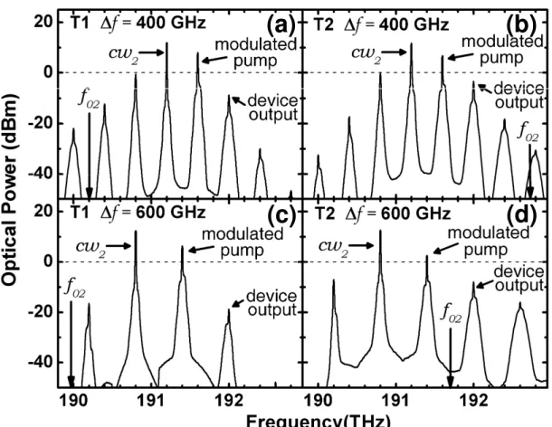
second-stage output spectra presented in Fig. 6. Figures 6(a) and 6(b) show the pump signal is slightly
more depleted for devices with T2 stages than with T1 stages when
∆
=
400 GHz. Interestingly,optical regeneration is also somewhat better for devices with T2 stages. A similar picture is also found
in Figs. 6(c) and 6(d) when
∆
=
600 GHz. However, in this case the depletion and the opticalregeneration are much more expressive. This scenario suggests the modulated pump depletion is a
required condition for the optimization of FWM regenerators. As discussed in [5, 13, 17], the
depletion of the modulated pump (which is also the signal to be regenerated) increases as the
nonlinear phase mismatching factor ∆ 0 decreases and vice-versa. Similarly, as can be easily checked from (3), FWM efficiency η also increases as ∆ 0 decreases. Therefore, higher η seems to be closely linked to pump depletion and better regeneration.
Fig. 6. Spectrum output at the second stage for devices with T1 and T2 stages and different spectral separation. (a) T1 and "f= 400 GHz, (b) T2 and "f= 400 GHz, (c) T1 and "f= 600 GHz, and T2 and "f= 600 GHz.
(a)
(b)
In [3], for the regenerators investigated, the modulated pump was not depleted, what led the authors
to the frequency restriction regarding devices design.
The spectra also help to explain the BER behavior displayed in Fig. 5. The regenerator performance
improves as ∆ increases until reaching ∆ =
600 GHz
(optimal regeneration), after whatperformance starts decreasing. This can be understood as follows: the smaller∆ is, the closer will be
the FWM sidebands and there will be more signal crosstalk. On the other hand, the greater ∆ is, the
farther apart will be the FWM sidebands and there will be less crosstalk, but, at the same time, pump
depletion will decrease. However, as per the current discussion, pump depletion seems to play a
fundamental role in the regeneration process. Therefore, as seen in Fig. 5, when ∆ =600 GHz, the
best trade-off between FWM crosstalk and FWM reshaping is reached and, consequently, the optical
regeneration is optimal. Fig. 7 shows the static transfer functions for regenerators with T1 and T2
stages for ∆ =
500 and 600 GHz
, respectively. As it might be anticipated from the previousresults, the step-like feature, typical of a regenerator, is more pronounced for a device with a T2 stage
than with a T1 stage. Finally, in Fig. 8 it is presented the optical power consumption per stage as
function of ∆ and calculated at the fiber inputs, that is, by summing the modulated pump and
continuous wave power (cf. Table I). Most notably, optical power consumptions for the
second-stage
seem to mirror somehow the results in Fig.5 for T2 devices. It is because, the higher the optical power
consumption, the higher the depletion and the better the regeneration. For T1 devices, it does not
happen because of the frequency restriction stated in [3].
CONCLUSION
In this work we discussed the design of pump-modulated fiber-FWM 2R optical regenerators by
means of simulations. A routine that implements a GA was used to optimize the devices. The
regenerators performances were assessed by comparing the input and output signals BERs. Our
investigation showed optimal optical regeneration takes place when there is pump depletion and an
appropriate choice of frequency separation between the signals that interfere via FWM. The latter one
is responsible for a trade-off between FWM crosstalk and FWM reshaping, a feature that has not been
reported in the literature yet. By testing the optimized regenerators, it was observed a significant BER
improvement of almost ten orders of magnitude. Furthermore, it was shown by using a procedure
reported in [3] the BER improvement would only be of six orders of magnitude for the same input
signal.
The deployment of the proposed frequency-shift-free regenerators would avoid the network
management needed to reallocate transmission channels, in contrast to what happens to conventional
FWM regeneration schemes. Finally, the strategy presented in this letter could be easily adapted to
design FWM optical regenerators for other modulation formats as, for example, QPSK signals [7].
ACKNOWLEDGMENT
This work was supported by CNPq grant no. 574017/2008-9 and FAPESP grant 08/57857-2.
Authors also thank VPIphotonics for VPItranmissionmaker™ academic licenses and Prof. M. L. F
Abbade for invaluable discussions.
REFERENCES
[1] P. V. Mamyshev, “All-optical data regeneration based on self-phase modulation effect,” in Proc. 24th European Conference on Optical Communications, 1998, pp. 475-476.
[2] E. Ciaramella, F. Curti, and S. Trillo, “All-optical signal reshaping by means of four-wave mixing in optical fibers,”
IEEE Photon. Technol. Lett. 13, pp.142–144, 2001.
[3] A. Bogris, D. Syvridis, “Regenerative properties of a pump-modulated four-wave mixing scheme in dispersion shifted fibers,” J. Lightw. Technol. 21, pp. 1892-1902, 2003.
[4] M. Rochette, L. Fu, V. Ta’eed, D. J. Moss, and B. J. Eggleton , “2R optical regeneration: an all-optical solution for BER improvement,” IEEE J. Sel. Topics in Quantum Electron. 12, pp. 736–744, 2006.
[5] R. Slavík, Bogris, F. Parmigiani, J. Kakande, M. Westlund, M. Sköld, L. Grüner-Nielsen, R. Phelan, D. Syvridis, P. Petropoulos,and D. J. Richardson, "Coherent all-optical phase and amplitude regenerator of binary phase-encoded signals," IEEE J. Sel. Topics in Quantum Electron.18, pp.859-869, 2012.
[6] P. Runge, C.-A. Bunge, K.Petermann, "All-optical wavelength conversion with extinction ratio improvement of 100 Gb/s RZ-signals in ultralong bulk semiconductor optical amplifiers," IEEE J. Sel. Topics in Quantum Electron.46, pp.937-944, 2010.
[7] A. Fragkos, A. Bogris, D. Syvridis, “All-optical regeneration based on phase-sensitive nondegenerate four-wave mixing in optical fibers,” IEEE Photon. Technol. Lett. 22, pp. 1826-1828, 2010.
[8] Gao Mingyi, J. Kurumida, and S. Namiki, “43-Gb/s operation of wavelength-tunable optical parametric regenerator,” IEEE Photon. Technol. Lett. 23, pp. 718-720, 2011.
[9] R. Slavík, F. Parmigiani, J. Kakande, C. Lundström, M. Sjödin, P. A. Andrekson, R. Weerasuriya, S. Sygletos, A.D. Ellis, L. Grüner-Nielsen, D. Jakobsen, S.Herstrøm, R. Phelan, J. O’Gorman, A. Bogris, D. Syvridis, S. Dasgupta, P. Petropoulos, and D. J. Richardson, “All-optical phase and amplitude regenerator for next-generation telecommunications systems,” Nat. Photon. 4, pp. 690–695, 2010.
[10]E.A.M. Fagotto, M.L.F. Abbade,”Wavelength-shift-free all-optical 2R regeneration via four-wave mixing, in Proc.
IEEE Photonics 2011, Arlington, VA, USA, pp.563-564.
[11]D. E. Goldberg, Genetic Algorithms in Search, Optimization, and Machine Learning, Addison-Wesley Longman Publishing Co, 1989.
[12]G. P. Agrawal, Nonlinear Fiber Optics, 4th. ed. New York: Academic Press, 2006.
[13]S. Song, C. T. Allen, K. R. Demarest, and R. Hui, “Intensity-dependent phase-matching effects on four-wave mixing in optical fibers,” J. Lightw. Technol. 17, pp. 2285–2289, 1999.
[14]M.L.F. Abbade, J. D. Marconi, R. L. Cassiolato, V. Ishizuca, I. E. Fonseca, and H. L. Fragnito, “Field-Trial Evaluation of Cross-Layer Effect Caused by All-Optical Wavelength Converters on IP Network Applications,” J. Lightw. Technol.
[15]D. Marcuse, “Derivation of analytical expressions for the bit-error probability in lightwave systems with optical amplifiers,” J. Lightw. Technol. 8, pp. 1816-1823, 1990.
[16]VPIphotonics GmbH, VPItransmissionMaker™ Optical Systems User’s Manual, Germany, 2013.