Abstract— We present a holey fiber (HF) with elliptical air-holes located in the center core area that ensures high birefringence, near-zero ultra-flattened chromatic dispersion and very low confinement losses in a wide wavelength range. The finite element method with perfectly matched boundary layer is used to investigate the guiding properties. It is demonstrated that it is possible to design a low-loss dispersion-flattened HF with a high birefringence of 0.0033 at a 1.55 m wavelength. According to simulation, near-zero ultra-flattened dispersion of 0 ± 0.5 ps/nm/km is obtained in a 1.25 to 1.65 m wavelength range with low confinement losses of 0.0008 dB/km in the entire band of interest.
Index Terms—Holey fiber, birefringence, chromatic dispersion, confinement loss.
I. INTRODUCTION
Index guiding photonic crystal fibers (PCFs) or holey fibers [1] usually consist of a hexagonal
arrangement of microscopic air-channels running down the length of the silica based fiber
surrounding a central solid silica core. Holey fibers (HFs) guide the light via one of two mechanisms:
effective-index guidance and photonic-bandgap (PBG) guidance. In the HFs with effective-index
mechanism, the light is guided based on the total internal reflection between a solid core and a
cladding region with multiple air-holes [1]. On the other hand, HFs based on PBG has the capability
to control the guidance of light within a certain frequency band [2]–[3]. Holey fibers have drawn
increased attention nowadays because of many of their attractive properties [4]; for example, very
high or very low nonlinearity, wideband dispersion-flattened characteristics, high birefringence,
endlessly single mode guiding, and many others.
By modulating the parameters of the holey cladding, it is possible to design application specific
guiding properties [5]. In this study, we have proposed a birefringent HFs, comprising of hexagonal
lattice of air holes, where four elliptical holes are inserted in the center core area (two elliptical
air-Design of Highly Birefringent Holey Fibers
with Near-Zero Ultra-flattened Chromatic
Dispersion and Ultralow Confinement Loss
M. Samiul Habib*, M. Selim Habib
Dept. of EEE, Rajshahi University of Engineering & Technology, Rajshahi-6204. Email: *[email protected]
S. M. A. Razzak, M. A. Goffar Khan
Dept. of EEE, Rajshahi University of Engineering & Technology, Rajshahi-6204. Y. Namihira and M. A. Hossain Graduate School of Engineering and Science, University of the Ryukyus, 1 Senbaru, Nishihara, Okinawa
holes in first ring and second ring also contains two elliptical air-holes) to achieve highly birefringent
fibers ensuring with flattened dispersion in the entire band of interest.
Birefringence is usually an undesirable property of fiber optics. In many sensing applications and in
applications where light is required to maintain a linear polarization state, a high level of
birefringence is often required [6]. Birefringent HFs can simply be realised [8] compared to
conventional fibers, since the refractive index contrast between the core and the cladding is higher
than the refractive index contrast of conventional fibers. The key point in realizing the birefringence is
to destroy the symmetry of the fiber structure and increase the effective index difference between the
two orthogonal polarization modes [6]. The structural symmetry can be destroyed either by altering
the air hole sizes near the core area [7]–[8], or by distorting the shape of the air holes (elliptical air
holes) [9]. There are a number of ways of designing birefringence in HFs. One common technique is
to break the HFs structural symmetry by inserting elliptical air hole along two orthogonal axes near
the core region. This results in increasing the difference between the effective indexes of the
orthogonal polarization modes. For many applications it is essential to design HFs that exhibit
simultaneous high birefringence, low confinement losses, small effective area, low and flattened
chromatic dispersion in a wide wavelength range. In broadband communications systems, fiber
dispersion and confinement loss play very important roles. For example, in wavelength division
multiplexing systems it is essential to maintain a uniform response in different wavelength channels.
This is strictly achieved by ensuring ultra-flattened dispersion characteristics of fibers [10]. This novel
property of HFs helps in tuning transmission characteristics namely dispersion, nonlinearity, and
confinement loss in smart ways.
II. DESIGN METHODOLOGY
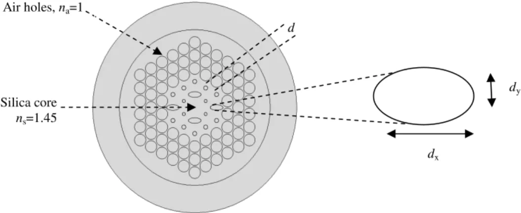
Fig. 1 shows a simple geometry of the proposed highly birefringence dispersion flat holey fiber
(HBDF-HF). The air-hole diameters on the first ring and second ring is d1, d2, while air-hole
diameters on the 3rd to 5th ring is same d and diameter of elliptical air-holes on first ring and second
ring in x direction is dx and in y direction is dy. The air-hole pitch is . The refractive index of the air
hole and fiber silica is na = 1 and ns = 1.45 respectively. As shown in Fig. 1, there are three degrees of
freedom, namely d1, d2 and for controlling the dispersion nature of the five-ring HF. Dimension of
the first ring is scaled down to flatten the dispersion characteristics. Birefringence can be achieved
over creating asymmetry, either by alerting the air hole size or distorting the shape of the air holes into
elliptical size in the core area. In Fig. 1 the background material is pure silica surrounding with
Fig. 1 Geometry of proposed five-ring HBDF-HF with 1st ring air-hole diameter d1, 2nd ring air-hole diameter d2, 3rd to
5th ring diameter is same d, diameter of elliptical air-holes on first ring and second ring in x direction (major axis) is dx and
in y direction (minor axis) is dy, air-hole pitch and number of ring, Nr=5.
III. SIMULATION METHODOLOGY AND EQUATION
The COMSOL software 4.2 version is used as a simulation tool. The finite-element method with
perfectly matched boundary layers (PML) is used to calculate effective refractive index,
birefringence, chromatic dispersion, and confinement loss of HFs. The FEM directly solves the
Maxwell equations to best approximate the value of the effective refractive index. Once the modal
effective refractive index, neff is obtained by solving an eigen value problem drawn from Maxwell
equations using the COMSOL software 4.2, birefringence, chromatic dispersion, and confinement loss
of HFs can be easily calculated.
Chromatic Dispersion
Chromatic dispersion is one of the most important modal properties of the HFs. Chromatic
dispersion is composed of material and waveguide dispersion. Control of chromatic dispersion is very
crucial for practical applications to optical fiber communication system. Chromatic dispersion D can
be obtained using the following relation [11]
2
2
Re[ ]
( ) d neff
D
c d
λ λ
λ
= − (1)
where Re[neff] is the real part of effective refractive index neff , is the wavelength, c is the velocity
of light in vacuum. The material dispersion given by Sellmeier formula is directly included in the
calculation. Therefore, D in (1) corresponds to the chromatic dispersion of the HF.
Confinement Loss
The confinement loss is a phenomenon whereby part of the guided light penetrates to the cladding
region. Due to similar refractive index between core and cladding optical field may penetrate into the Air holes, na=1
Silica core ns=1.45
dy
dx
cladding region results confinement loss. Actually number of air holes in the cladding region limits
the confinement loss.
The confinement loss Lc is obtained from the imaginary part of refractive index neff as follows [10]
Lc = 8.686 ×k0 Im[neff] × 10 3
dB/km (2)
where Im[neff] is the imaginary part of the refractive index, k0 = 2 / is the wave number in the free
space.
Birefringence and Beat Length
Birefringent HFs can be achieved by having asymmetric core. This increases the effective index
difference between the two orthogonal polarization modes. Birefringence is defined as a difference
between effective refractive indices of two fundamental polarization modes [7], [12] and can be
written as
B=|nx- ny| (3)
Where nx and ny are the effective refractive indices of each fundamental mode.
The beat length LB which can be defined as follows [13]
LB= /B (4)
where is the operating wavelength.
IV. SIMULATION RESULTS
In this proposed design, air -hole diameter of the inner ring and hole-to-hole spacing effects, on the
birefringence, chromatic dispersion and confinement losses are carefully investigated. Optimizing the
geometrical parameters, such as air-hole diameters and pitch , the ultra-flattened chromatic
dispersion with high birefringence HF can be efficiently designed. In our simulation we first set
air-hole diameters of the outer cladding at d / = 0.9. In the outer most cladding a high value normalized
diameter is chosen for better field confinement. Dimension of the first ring is lowered down to flatten
the dispersion characteristics. As shown in Fig. 1, there are three modest number of tuning parameters
namely d1, d2 and for shaping the dispersion behavior of the five-ring HF. At shorter operating
wavelengths, mode is more confined in the core region than at longer wavelengths, and the chromatic
dispersion is directly affected from the inner air-hole ring and the air hole arrangements but also from
Fig. 2 (a) shows an example of the effect of changing d1/ on the dispersion slope for x polarization
with d1/ =0.22, 0.24, and 0.26 respectively, for a fixed air-hole pitch =1.42 m, outer ring
normalized air-hole diameter d/ =0.9 and dx=1.42 m, dy=0.608 m.
(a) (b)
Fig. 2 (a) Effect of d1/ on the dispersion slope for x polarization with d1/ =0.22, 0.24 and 0.26 respectively, outer ring
normalized diameter d/ =0.9, d2/ =0.32 dx/ =1 and dy/ =0.428 and fixed air-hole pitch =1.42 m.
(b) Effect of changing on the dispersion level for x polarization with d1/ =0.22, d2/ =0.32, d/ =0.9, dx/ =1 and
dy/ =0.428.
From Fig. 2 (a) it has been seen that flattened dispersion is greatly depend on first ring normalized
air-hole diameter d1/ . The dispersion is flat as d1/ =0.22 but the dispersion slope changes
significantly from the positive slope to negative one near the wavelength at 1.23 m as d1/ = 0.24
and d1/ = 0.26.
Fig. 2 (b) shows effect of changing pitch, on the dispersion behavior. From designing point of
view, a large value of d/ is chosen for better field confinement. Simulation result reveals that the
air-hole pitch, dominantly influence the dispersion level but insignificant effect on the slope of the
dispersion.
1 1.1 1.2 1.3 1.4 1.5 1.6 1.7 1.8 1.9 2
-10 -5 0 5 10 15 20
Wavelength λλλλ [µµµµm]
C h r o m a ti c D is p e r si o n D [p s/ (n m .k m )] Λ Λ Λ
Λ=1.42, d
1/ΛΛΛΛ=0.22 d2/ΛΛΛΛ=0.32 d/ΛΛΛΛ=0.9 dx=1.42 dy=0.608
Λ Λ Λ
Λ=1.42, d1/ΛΛΛΛ=0.24 d2/ΛΛΛΛ=0.32 d/ΛΛΛΛ=0.9 dx=1.42 dy=0.608
Λ Λ Λ
Λ=1.42, d
1/ΛΛΛΛ=0.26 d2/ΛΛΛΛ=0.32 d/ΛΛΛΛ=0.9 dx=1.42 dy=0.608
1 1.1 1.2 1.3 1.4 1.5 1.6 1.7 1.8 1.9 2
-20 -15 -10 -5 0 5 10 15 20
Wavelength λλλλ [µµµµm]
C h r o m a ti c D is p e r si o n D [p s/ (n m .k m )] Λ Λ Λ
Λ=1.23, d
1/ΛΛΛΛ=0.22 d2/ΛΛΛΛ=0.32 d/ΛΛΛΛ=0.9
Λ Λ Λ
Λ=1.28, d
1/ΛΛΛΛ=0.22 d2/ΛΛΛΛ=0.32 d/ΛΛΛΛ=0.9
Λ Λ Λ
Λ=1.30, d
1/ΛΛΛΛ=0.22 d2/ΛΛΛΛ=0.32 d/ΛΛΛΛ=0.9
Λ Λ Λ
Λ=1.42, d
(a) (b)
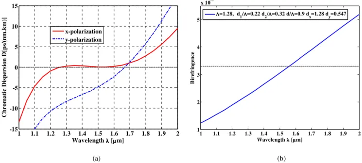
Fig. 3 (a) Optimum dispersion of the proposed HBDF-HF for =1.28, d1/ =0.22, d2/ =0.32, d/ =0.9, dx/ =1 and
dy/ =0.428.
(b) Wavelength dependence of birefringence of the proposed HBDF-HF for optimum design parameters: =1.28, d1/ =0.22,
d2/ =0.32, d/ =0.9, dx/ =1 and dy/ =0.428.
Fig. 3 (a) shows dispersion property of the HBDF-HF for both x-polarization and y-polarization.
Optimizing the geometrical parameters, ultra-flattened dispersion of 0 ± 0.5 ps/nm/km is obtained in a
1.25 m to 1.65 m wavelength range (400 nm flat bandwidth) for x-polarization. For optimum result,
hole diameter on the first ring is scaled down to shape dispersion property while diameter of
air-holes on outer rings is kept larger to reduce the confinement loss. Dispersion at 1.55 m is as low as
0.072 ps/nm/km for x-polarization.
From our simulation result it is seen that, effective index of y-polarization mode is higher than
x-polarization mode. Fig. 3 (b) shows variation of the modal birefringence as a functionof wavelength
with =1.28, d1/ =0.22, d2/ =0.32, d/ =0.9, dx/ =1 and dy/ =0.428. This proposed design can
operate effectively as a single mode fiber with a high birefringence of 0.0033 at a 1.55 m
wavelength. In terms of birefringence our proposed HF structure exhibits much better performances
than [6], [7] and [13].
1 1.1 1.2 1.3 1.4 1.5 1.6 1.7 1.8 1.9 2
-15 -10 -5 0 5 10 15
Wavelength λλλλ [µµµµm]
C
h
r
o
m
a
ti
c
D
is
p
er
si
o
n
D
[p
s/
(n
m
.k
m
)]
x-polarization y-polarization
1 1.1 1.2 1.3 1.4 1.5 1.6 1.7 1.8 1.9 2
1 2 3 4 5
x 10-3
Wavelength λλλλ [µµµµm]
B
ir
ef
r
in
g
e
n
ce
Λ ΛΛ Λ=1.28, d
(a) (b)
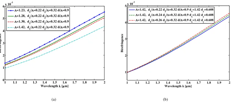
Fig. 4 (a) Wavelength dependence of birefringence of the proposed HBDF-HF for: d1/ =0.22, d2/ =0.32, d/ =0.9, dx/ =1
and dy/ =0.428 and =1.23, 1.28, 1.30, 1.42 m.
(b) Wavelength dependence of birefringence of the proposed HBDF-HF for: d2/ =0.32, d/ =0.9, dx/ =1 and dy/ =0.428,
=1.42 m and d1/ =0.22, 0.24, 0.26.
From Fig. 4 (a) it can clearly seen that, birefringence is sensitive to air-hole pitch. As hole-to-hole
spacing decreases, the birefringence increases. So in order to achieve higher birefringence, we
decreased the hole-to-hole spacing from 1.42 m to 1.23 m.
Our simulations show that there is a tradeoff between low dispersion and birefringence. When the
inner-ring air hole size increases the birefringence improves, however, the dispersion slope degrades.
From Fig. 4 (b) it is seen than as d1/ increases birefringence improves but dispersion slope
deteriorates as seen from Fig. 2 (a). In Fig. 5 (a), we have plotted the variation of the beat length as a
function of the wavelength. Highly birefringence fibers have low beat length. Our proposed design
has low beat length of 0.474 mm at the operating wavelength which is less than reported in [6].
The confinement loss strongly depends on the number of air hole rings, air hole diameter and
hole-to-hole spacing. In our proposed design, dimension of the outer three rings are kept larger to reduce
the confinement loss. Confinement losses of the HF reported in [6], [7] and [13] are very large which
is 2.5×10⁻¹dB/km, 1.21×10⁷dB/km and 4.6×10⁶ dB/km at the operating wavelength =1.55 m.
1 1.1 1.2 1.3 1.4 1.5 1.6 1.7 1.8 1.9 2 1
2 3 4 5x 10
-3
Wavelength λλλλ [µµµµm]
B
ir
e
fr
in
g
en
ce
Λ Λ Λ Λ=1.42, d
1/ΛΛΛΛ=0.22 d2/ΛΛΛΛ=0.32 d/ΛΛΛΛ=0.9 dx=1.42 dy=0.608
Λ Λ Λ
Λ=1.42, d1/ΛΛΛΛ=0.24 d2/ΛΛΛΛ=0.32 d/ΛΛΛΛ=0.9 dx=1.42 dy=0.608 Λ
Λ Λ
Λ=1.42, d1/ΛΛΛΛ=0.26 d2/ΛΛΛΛ=0.32 d/ΛΛΛΛ=0.9 dx=1.42 dy=0.608
1 1.1 1.2 1.3 1.4 1.5 1.6 1.7 1.8 1.9 2
0 1 2 3 4 5 6x 10
-3
Wavelength λλλλ [µµµµm]
B
ir
e
fr
in
g
e
n
ce
Λ Λ Λ Λ=1.23, d
1/ΛΛΛΛ=0.22 d2/ΛΛΛΛ=0.32 d/ΛΛΛΛ=0.9
Λ Λ Λ
Λ=1.28, d1/ΛΛΛΛ=0.22 d2/ΛΛΛΛ=0.32 d/ΛΛΛΛ=0.9
Λ Λ Λ Λ=1.30, d
1/ΛΛΛΛ=0.22 d2/ΛΛΛΛ=0.32 d/ΛΛΛΛ=0.9
Λ Λ Λ Λ=1.42, d
(a) (b)
Fig. 5(a) Beat length of the proposed HBDF-HF for optimum design parameters as a function of wavelength.
(b) Confinement loss of the proposed HBDF-HF for optimum design parameters as a function of wavelength.
This is due to the small number of air-hole rings that have been used in [7] and [13]. However, in
our proposed design, confinement loss is 0.0008 dB/km at the operating wavelength =1.55 m.
When the diameter of the inner air hole rings is increased, the confinement loss reduced significantly
but control of chromatic dispersion is somewhat difficult at shorter wavelength. Fig. 5 (b) shows
wavelength dependence of confinement loss for x-polarization. Confinement loss at 1.55 m is as low
as 0.0008 dB/km for x-polarization.
Therefore, the proposed fiber with a modest number of design parameters, near-zero ultra-flattened
dispersion, and leakage properties may pave the way for different applications in optics including
optical parametric amplification, wavelength conversion, soliton pulse systems, and so on.
V. CONCLUSION
A truly near zero ultra-flattened chromatic dispersion with high birefringence and low confinement
loss HF has been proposed in a broad wavelength range. It has been shown through numerical
simulation results that a five-ring HBDF-HF can assume nearly zero ultra-flattened dispersion of 0 ±
0.5 ps/nm/km in a 1.25 to 1.65 m (400 nm flat band) wavelength range with high birefringence of
0.0033 and low confinement losses of 0.0008 dB/km at 1.55 m. This proposed HBDF-HF design
1 1.1 1.2 1.3 1.4 1.5 1.6 1.7 1.8 1.9 2
3 4 5 6 7 8 9
10x 10
-4
Wavelength λλλλ [µµµµm]
B
e
a
t
L
e
n
g
th
Λ Λ Λ
Λ=1.28, d
1/ΛΛΛΛ=0.22 d2/ΛΛΛΛ=0.32 d/ΛΛΛΛ=0.9 dx=1.28 dy=0.547
1.3 1.4 1.5 1.6 1.7 1.8 1.9 2
10-10 10-5 100
Wavelength λλλλ [µµµµm]
C
o
n
fi
n
e
m
e
n
t
L
o
ss
L
c
[
d
B
/K
m
]
Λ ΛΛ Λ=1.28, d
with highly birefringence nearly zero flattened chromatic dispersion and low confinement losses can
be widely used for polarization control in fiber-optic sensors and optical communication systems.
This fiber has a modest number of design parameters, five rings, two air-hole diameters, and a
common air-hole pitch.
REFERENCES
[1] J. C. Knight, T. A. Birks, P. St. J. Russell, and D. M. Atkin, “All-silica single-mode optical fiber with photonic crystal cladding,” Opt. Lett., vol. 21, pp.1547-1549 Oct. 1996.
[2] T. A. Birks, J. C. Knight, B. J. Mangan, and P. S. J. Russell, “Photonic crystal fibers: An endless variety,” IEICE Trans. Electron., vol. E84-C, pp. 585–592, 2001.
[3] J. Broeng, D. Mogilevstev, S. E. Barkou, and A. Bjarklev, “Photonic crystal fibers: A new class of optical waveguides,” Opt. Fiber Technol., vol. 5, pp. 305–330, 1999.
[4] S. M. A. Razzak, Y. Namihira, and F. Begum, “Ultra-flattened dispersion photonic crystal fiber,” Electron. Lett., vol. 43, pp. 615–617, 2007.
[5] K. Saitoh, N. J. Florous, and M. Koshiba, “Ultra-flattened chromatic dispersion controllability using a defect-core photonic crystal fiber with low confinement loss,” Opt. Express, vol. 13, pp. 8365–8371, 2005.
[6] H. Ademgil and S. Haxha, “Highly Birefringent Photonic Crystal Fibers With Ultralow Chromatic Dispersion and Low Confinement Losses,” J. Lightwave Technology, vol. 26,pp. 441-448, 2008.
[7] J. Ju, W. Jin, and M. S. Demokan, “Properties of a highly birefringent photonic crystal fiber,” IEEE Photon. Technol. Lett., vol. 15, no. 10, pp. 1375–1377, Oct. 2003.
[8] T. Nasilowski, P. Lesiak, R. Kotynski, M. Antkowiak, A. Fernandez, F. Berghmans, and H. Thienpont, “Birefringent photonic crystal fiberas a multi parameter sensor,” in Proc. Symp. IEEE, 2003, pp. 29–32.
[9] Y. Yue, G. Kai, Z. Wang, T. Sun, L. Jin, Y. Lu, C. Zhang, J. Liu, Y. Li, Y. Liu, S. Yuan, and X. Dong, “Highly birefringent elliptic-hole photonic crystal fibre with squeezed hexagonal lattice,” Opt. Lett., vol. 32, pp. 469–471, 2007. [10]A. Ferrando, E. Silvestre, P. Andres, J. J. Miret, and M. Andres, “Nearly zero ultraflattened dispersion in photonic
crystal fibers,” Opt. Lett., vol. 25, pp. 790–792, 2000.
[11]K. Saitoh, M. Koshiba, T. Hasegawa, E. Sasaoka, “Chromatic dispersion control in photonic crystal fibers: application to ultra-flattened dispersion,” Opt. Express, vol. 11, no. 8, pp.843-852, April 2003.
[12]K. Saitoh and M. Koshiba, “Full-vectorial imaginary-distance beam propagation method based on a finite element scheme: Application to photonic crystal fibers,” IEEE J. Quantum Electron., vol. 38, no. 7, pp. 927–933, Jul. 2002. [13]A. Ortigosa-Blanch, J. C. Knight, W. J. Wadsworth, J. Arriaga, B. J. Mangan, T. A. Birks, and P. S. J. Russell, “Highly