Rafael Gonçalves Licursi de Mello
Força Aérea Brasileira , Laboratório de RF -UFSC [email protected] Cynthia Junqueira
P &D Department – Espectro Ltda., FEEC-UNICAMP [email protected]
Abstract— Polarization diversity antenna arrays are applied to electronic support measures (ESM) systems since the 1980s. However, even today modern systems are conceived with the employment of the traditional and inconvenient spiral antennas and there are no studies that evidences most of the benefits of this technique applied to them. This paper aims at showing not only the advantages on polarization matching issues, but also the benefits in gain, in simpler truncation effect problems and in costs and time spent on design and production. After a brief approach strictly applied to ESM of the main features of spiral antennas and bow-tie antennas compounding a polarization diversity array, equations of the power available from the last were developed from the concept of effective length. The results demonstrate that the array could provide a power 8.7 dB higher than a modern spiral would to an ESM system when it receives vertical or horizontal linearly polarized waves, which multiplies by 2.7 the range of the system, besides also presenting a better performance in case of circularly polarized incident waves. This work has contributed to propose a replacement to the very common use of spiral antennas on the upcoming ESM system projects. This study is recommended for the areas of Electronic Warfare, Electromagnetic Devices and Applications and Ultra-Wideband Antennas.
Index Terms— bow-tie antennas, electronic support measures, polarization
diversity antenna array, spiral antennas.
I. INTRODUCTION
Even though one of the Electronic Warfare trends is to explore frequency ranges beyond
radiofrequency (RF), the eternal conflict between radars and electronic support measures (ESM)
systems, which began on the 20th century, still has a prime importance in the military context. On this
conflict, every wasted dB could mean an unsuccessful detection; every non-well calibrated radiation
pattern anomaly could succeed in an inaccuracy of measurement. These can result in a mission failure.
Polarization diversity antenna arrays are applied to ESM systems since the early 1980s. However,
although exist lots of studies about this technique, most of them are about mobile phone networks [1],
RFID [2] and WLAN [3] applications, HF [4] and optical [5] communications. None of them studies
most of the benefits of polarization diversity applied to ESM systems. Even those focused on
ultra-wideband antennas [6], that would be interesting to these military systems, do not. Besides that, many
modern ESM systems are still designed with the traditional and inconvenient spiral antennas.
This brief shows not only the mathematical demonstration of combining signals generated in a
couple of bow-tie antennas, but also the benefits in gain, in less unfavorable truncation effect issues,
and in the fact that they are cheaper and easier to be designed, computer simulated and produced,
compared to the classical spirals.
The goal of this effort, besides demonstrating the above subjects, is to explicit that the ultimate
technologies allow this traditional and inconvenient employment to be replaced by polarization
diversity antenna arrays.
II. ANTENNAS APPLIED TO ESMSYSTEMS
A. Electronic Support Measures Systems
The ESM systems are designed to intercept, characterize, identify and locate RF emitters through
the passive monitoring of the electromagnetic environment. They could be considered successful
when confronting the most advanced modern radars as they "detect while staying undetected", and, to
do that, they must be able to receive and process the weakest and furthest transmitted signal [7].
The performance of such equipment depends, among other factors, on the sensitivity and the
internal losses inherent to the components of their receivers, but, specifically, the antennas and their
polarization matching with the incident waves are the first aspects to be considered [8].
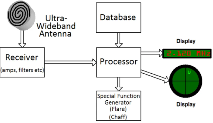
Fig. 1 shows a generic ESM system architecture. On this paper, the receiver, the processor, the
database, the special function generator and the displays are not under analysis.
Fig. 1. Generic ESM system.
Depending on the application, an ESM system can measure various parameters of received signals.
One of them has tactical and strategical importance and it is known as direction of arrival (DOA). It
reveals the direction from where the radar emits the signal.
The simplest reliable way of getting DOA is called the amplitude comparison method, in which it
is necessary that the system has an antenna array covering the sector of interest. The antennas must
have a characteristic radiation pattern, with a main lobe basically covering its respective sector of
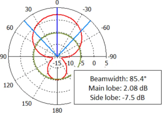
interest, and less expressive side lobes [9]. Fig. 2, obtained on CST software [10], illustrates a typical
radiation pattern of antennas that would be appropriate to compound an array of six units, each one
responsible for covering 60° of azimuth. The beamwidth of 85.4° covers the sector of interest. The
Fig. 2. Typical radiation pattern of an appropriated antenna to the amplitude comparison method.
Fig. 3 illustrates the amplitude comparison method. When the six-unit array, represented in the
left, receives a signal, a specific voltage is generated in each antenna, in reason of their angular
disposition. The evaluation of DOA is made by the ESM system as shown in the right.
Fig. 3. The amplitude comparison method.
The calibration of the system and the measurement of DOA through this method will be as easy
and accurate as the radiation patterns of each array unit are regular ones. If the patterns do not reach a
minimum regularity, this important parameter will be unmeasurable.
The ESM systems may be installed on several types of platform, such as warships, trucks, aircraft
and satellites. Some, especially the last two, could present serious limitations in weight and volume.
B. Ultra-Wideband Antennas
The ESM systems are made to cover a wide range of frequencies and thus confront all the radars
on that whole range. To achieve this, ultra-wideband antennas, which operate in the proportion of
20:1, or even 40:1, are usually employed.
These objects were developed from theoretical antennas, called by Rumsey as frequency
independent antennas [11]. To be frequency independent, antennas must be determined by angles,
As it is not possible the real manufacturing of an infinite-dimensional antenna, as it is limited to a
practical size, the truncation effect arises. It comes from the unwanted reflection of the electrical
current at the end of the antenna conductors, causing several drawbacks, depending on the geometry
of the radiation antenna elements.
C. Measurement of DOA Using Spiral Antennas
The most common type of antenna used on ESM systems is the spiral antenna backed by a
conducting plane reflector, as illustrated in Fig. 4. They are employed because of their capability of
receiving waves with different kinds of polarization and their ultra-wideband operation, thus covering
a large class of radars, besides their low weight and volume.
Fig. 4. Spiral antenna backed by a conducting plane [10].
The typical radiation pattern of such antennas is similar to that of Fig. 2. Modern variations of
these devices could achieve a gain around 6.8 dBi [12].
The radiation elements geometry provides it right or left-handed circular polarization (RHCP or
LHCP), according to the rotation of the spirals. Because of that, this type of antenna causes
attenuation of 3 dB (if its axial ratio is equal to 0 dB) in case of linearly polarized (LP) incident waves
and it is practically unable to receive unmatched circularly polarized waves [13].
The calculation of DOA on systems which use spiral antennas is hampered when truncation effect
is significant. The current reflected at the open-ends runs through the conductive spirals in reverse,
producing new radiation polarized in the opposite hand of the original. This new radiation interacts
with the first, which induces irregularities in the radiation pattern, moves the maximum radiation axis
and increases the axial ratio. To reduce the truncation effect is one of the greatest challenges of
designers.
The lowest operating frequencies of a spiral, related to incident signals with the largest
wavelengths, are defined by its external diameter. The highest frequencies, related to the shortest
the manufacturing process also a major challenge, since it must be as accurate as it is expected to
achieve the highest frequencies.
Currently, spiral antennas can be developed, optimized and analyzed with the aid of
electromagnetic analysis software [14], which reduces costs and time spent on the project, besides
increasing its quality. Nevertheless, the dimensions of the conductors arranged in the shape of spirals
together with the complexity and the precision of techniques to reduce truncation effect contribute for
these simulations to be a slow process and to require high performance computers. These factors also
complicate the manufacturing and increase time and costs spent.
D. Measurement of DOA Using Polarization Diversity Bow-Tie Antenna Arrays
Bow-tie antennas could be applied in couples, orthogonally to each other, in order to satisfy the
need of ultra-wideband operation of ESM systems. These antennas are simplifications of biconical
antennas flattened in a plane, and they could also be compared to dipoles defined by angles, which
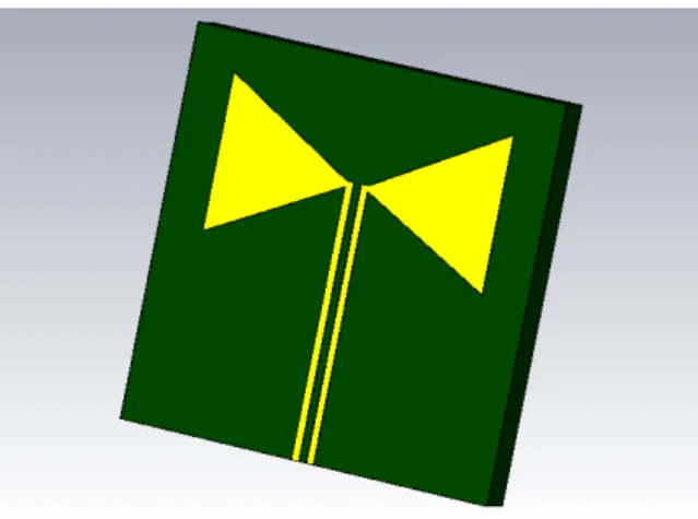
meet the conditions detailed by Rumsey. Fig. 5 exemplifies a bow-tie.
Fig. 5. Bow-tie dipole antenna.
The typical radiation pattern of a bow-tie is similar to a dipole one, i.e., omnidirectional. Reflectors
may be used in order to mold it and make it suitable to obtain DOA through the amplitude comparison
method. Modern devices have gain around 9.5 dBi [15].
These antennas are LP. Therefore, they receive RHCP and LHCP waves with attenuation of 3 dB,
and they are practically unable to receive LP waves in the transverse direction [13]. These
characteristics make one single isolated antenna not proper to constitute ESM systems, because it
would be impaired to detect a number of radars. However, by combining orthogonally two of them
this issue ceases. Advances on the area of miniaturization of antennas [16] and RF components [17]
have made possible previously inconceivable space arrangements. Because of that, the weight and
volume restrictions from aircraft and satellites nowadays may be circumvented.
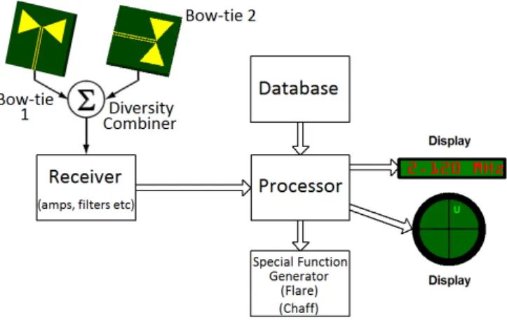
The two signals generated by the orthogonally arranged antennas must pass through a diversity
combiner switch. On this paper, the switch response is in equal-gain without a phase delay between
Fig. 6. Polarization diversity bow-tie antenna array on a generic ESM system, without phase shifting.
Fig. 7. Polarization diversity bow-tie antenna array on a generic ESM system, with phase shifting.
Truncation effect decreases the gain of bow-ties, as seen in the spirals. However, the axial ratio
problem does not appear on the polarization diversity antenna array because each antenna is
responsible for receiving one of the components of the incident signal.
The simplicity of the radiator elements of the bow-ties geometry, unlike the spirals, does not require
complicated manufacturing processes. It also facilitates the computer simulation of these objects.
Because of that, their design and manufacturing process tend to spend less time and costs than that of
the spirals.
III. MATHEMATICAL DEMONSTRATION OF POLARIZATION MATCHING OF COMBINER SWITCH
A. Enunciation
Consider the position located in the open-ends of a couple of antennas, both LP, one of
them disposed vertically V and the other horizontally H. Consider that they feed a diversity combiner
switch, which can operate in one of two forms mentioned above, i.e., providing on its output the sum
voltage of the two input signals without phase shifting, or providing this sum with phase delay of 90°
For comparative purposes, consider signals with different types of polarization but with the same
intensity that could stimulate the open-ends of such antennas. On position , the electric field
as a function of time of a LHCP incident wave, of a RHCP incident wave, of a linearly polarized
wave in a plane inclined at 45° between the orthogonal antennas (ILP), of a wave with horizontal
linear polarization (HLP) and other with vertical linear polarization (VLP) could be respectively
represented and defined as in (1) to (5) below:
(1)
(2)
(3)
(4)
(5)
where is the electric field amplitude and is the angular frequency. The factor applied to
HLP and VLP waves aims to consider, for comparative calculation purposes, the same amplitude and
the same incident power for all types of the above mentioned waves.
The voltage generated on the open-ends of an antenna can be evaluated from the concept of
effective length , defined as how much voltage it would generate when excited by a wave with
electric field amplitude [15]. Thus:
(6)
Applying the incident waves component of unit vector on the horizontally disposed antenna, H,
and the component of unit vector on the vertically disposed antenna, V, both of effective length
, the voltage phasor generated in specified by acronyms for different occasions are:
(7)
(8)
(9)
(10)
(11)
(12)
(13)
(14)
(15)
For matched impedances , the voltage drop across the internal impedance of the generator – the
antennas in this case – consists of 50% of the total. Thus, only 50% of voltage will reach the proposed
switch, whose equal-gain diversity combining equation when there is no phase shifting, like that
of Fig. 6, is presented in (17):
(17)
where is the conversion factor of the combiner switch. For input signals combined with phase
delaying on V, like that of Fig. 7, the equation is:
(18)
The instantaneous electrical power available at the output of the switch can be depicted as:
(19)
B. Numerical Calculation
Consider , , , and . Disregard the
mutual coupling, related on literature [6] to be less than -21 dB in a modern polarization diversity
array of antennas with similar radiation pattern and ultra-wideband behavior of bow-ties.
With the aid of Matlab software [18], numerically calculating the developed equations, the
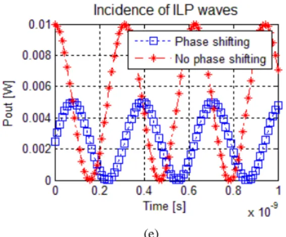
graphics shown in Fig. 8 from (a) to (e) are presented.
(a) (b)
(e)
Fig. 8. Combiner output power on different incident waves occasions: (a) HLP, (b) VLP, (c) RHCP, (d) LHCP and (e) ILP.
IV. ANALYSIS
The numerical calculation shows that for the case of HLP incident waves the polarization diversity
set simply receives the signal through the H antenna and transmits it through the combiner switch,
without any attenuation, as in Fig. 8.a.
Fig. 8.b reveals that, for the configuration of delay of the signal generated on the V antenna, there
will be phase delay also on instantaneous electric power in case of VLP incident waves, which in no
way would affect the operation of ESM systems.
In Fig. 8.c, for the case of RHCP waves, the power on the combiner switch output will double
when there is delay on the signal generated in the V antenna, since the two electrical components will
have its peaks added at once. There will be no increased signal in the case without phase shifting.
If there is incidence of LHCP waves, there will be no signal intensification or attenuation when the
configuration is without delay. However, for the example of combiner delaying the signal generated
in V antenna, the peak of an electric component would be added to the other’s valley, which
completely attenuate the signal at the output, as shown in Fig. 8.d. The set behavior on 8.c and 8.d
shows that it synthetically simulates a RHCP antenna when there is phase delaying on the V antenna.
The delay on the H antenna would simulate a LHCP antenna, instead of a RHCP one.
Fig. 8.e shows that when there is incidence of 45° ILP signals on the configuration without delay,
the components received by the two antennas are summed in phase, which causes the output power to
be twice as high as it would be if the incident signal was VLP or HLP. An orthogonal ILP signal
(-45°) would not be receivable, since its valleys and its peaks would cancel each other. Thus, an
angular disposition of the array of ±45° with the ground would increase a VLP or HLP signal in 3 dB.
This results show that the correct choice of the proper configuration of the combiner and of the
angular disposition of the array would be advantageous in front of spirals’ performance: (I) an angular
disposition of 0° of the array (one antenna on vertical and the other on horizontal), relative to the
ground, with no phase shifting would receive VLP or HLP with the 9.5 dBi from the mentioned
equals to 3.8 dBi, which means a 5.7 dB better performance of the bow-tie array. The same
configuration would receive both RHCP and LHCP with the same performance, which means 2.7 dB
better performance than spirals (and remember that a single spiral would not be able to receive both of
them); (II) an angular disposition of 0° of the array with 90° phase shifting on the signal generated on
one antenna would receive VLP or HLP signals with no attenuation, as in statement (I), but a RHCP
or LHCP signal would be received with 9.5 dBi plus 3 dB equals to 12.5 dBi by the array, again 5.7
dB higher than the spirals; (III) at last, an angular disposition of ±45° of the array, relative to the
ground, with no phase shifting, would receive VLP or HLP with 9.5 dBi plus 3 dB equals to 12.5 dBi,
8.7 dB higher than the 6.8 dBi minus 3 dB equals to 3.8 dBi performance that would be shown by a
spiral. The disadvantage from statement (III) option is the fact that VLP or HLP signals must be
chosen, while spirals receive both of them.
Electronic and mechanical maneuvers could be implemented to switch between the different
angular dispositions and phase shifting configurations, in order to obtain the greatest possible
advantages in front of different emitters.
This 8.7 dB higher intensity available power, applied on the ESM detection range equation [7],
together with the simplest truncation effect issues on the array radiation patterns, provides the ESM
system the capability of obtaining a more accurate measurement of DOA and other parameters from a
range of 2.7 times the range than it would obtain with spirals, with less costs and time spent on design
and production. The 5.7 dB factor found would multiply the range by 1.9 times and the 2.7 dB factor
by 1.4 times.
V. CONCLUSIONS
The power level has crucial importance in a conflict between a radar and an ESM system.
Although some polarization diversity devices applied to ESM systems have been develop in the
1980s, even today most of these military systems are conceived with spiral antennas.
This paper has shown that the spirals offer lots of inconveniences to those systems, like
polarization matching issues, low gain, critical truncation effects for DOA measurement, high costs
and time spent on designing, computer simulating and production.
In contrast, the absence of losses by polarization mismatching on a polarization diversity bow-tie
antenna array was mathematically demonstrated. Its simpler truncation effect issues, favorable for
DOA measurement, its faster and cheaper design, computer simulating and production were seen.
The results have shown that a polarization diversity bow-tie antenna array could provide for an
ESM system a power 8.7 dB higher than a modern spiral would when confronting HLP or VLP
radars, which would multiply by 2.7 the range of the system. They also presented that ESM systems
equipped with the array would be able to confront both RHCP and LHCP radars, unlike those
Taking into account the above mentioned factors, the replacement of traditional spiral antennas by
polarization diversity antenna arrays would be convenient on the upcoming ESM system designs.
VI.
A
CKNOWLEDGEMENTSThe authors would like to thank Adriane Marie Salm Coelho, Fernando Rangel de Sousa, Rodrigo
Vinícius Mendonça Pereira and Daniel Basso Ferreira, who provided insight and expertise that greatly
assisted the development of this work.
REFERENCES
[1] N. T. Duc, S. Shin. “A proposal antenna polarization diversity for LTE 2x2 MIMO in indoor testbed” in Proc. Seventh
Int. Conf. on Ubiquitous and Future Networks, 2015, pp. 35-36.
[2] E. -S. Yang, H. -W. Son. “Dual-polarised metal-mountable UHF RFID tag antenna for polarisation diversity”. Electronic Letters, vol. 52, issue 7, pp. 496-498, Apr. 2016.
[3] J. Zhu, S. Li, B. Feng, L. Deng, S. Yin. “Compact dual-polarized UWB quasi-self-complementary MIMO/diversity antenna with band-rejection capability”. IEEE Antennas and Wireless Propagation Letters, vol. 15, pp. 905-908, Sep. 2015.
[4] P. M. Ndao, Y. M. Erhel, D. Lemur, M. Oger, J. Le Masson. “First experiments of a HF MIMO system with
polarization diversity” in Proc. Int. Conf. on Ionospheric Radio Systems and Techniques, 2012, pp. 1-5.
[5] K. Suzuki, K. Tanizawa, S. -H. Kim, S. Suda, G. Cong, K. Ikeda, S. Namiki, H. Kawashima. “Polarization-rotator-free polarization-diversity 4x4 Si-wire optical switch”. IEEE Photonics Journel, vol. 8, issue 2, Feb. 2016.
[6] M. S. Khan, A. -D. Capobianco, A. Naqvi, B. Ijaz, S. Asif, B. D. Braaten. “Planar, compact ultra-wideband polarisation
diversity antenna array”. IET Microwaves, Antennas & Propagation, vol. 9, issue 15, pp. 1761-1768, Dec. 2015.
[7] R. G. Wiley. ELINT: The Interception and Analysis of Radar Signals. Boston: Artech House Inc., 2006.
[8] A. A. Heidari, M. Simrooni, M. Nakhkash. “Analysis and Design of an X-Band Microstrip Patch Array Antenna for
ESM Application”, in Proc. Int. Conf. on Electromagnetics in Advanced Applications, 2007, pp. 559-562.
[9] V. Alleva, D. Baccello, M. Bartocci, B. Orobello. “Digital Antenna Unit for DA Analyis in ESM Systems” in Proc. 7th
European Radar Conference, 2010, pp. 479-482.
[10] Computer Simulation Technology. “Studio Suite”. Internet: www.cst.com, 2016 [Apr. 10, 2016].
[11] V. H. Rumsey. Frequency independent antennas. New York: Academic Press Inc., 1966.
[12] H. Nakano, K. Kikkawa, N. Kondo, Y. Iitsuka, J. Yamauchi. “Low-profile equiangular spiral antenna backed by an
EBG reflector”. IEEE Transactions on Antennas and Propagation, vol. 57, issue 5, pp. 1309-1318, May 2009.
[13] C. A. Balanis. Antenna Theory: Analysis and Design. 3rd edition. Hoboken: John Wiley & Sons, Inc., 2005.
[14] H. Kogure, Y. Kogure e J. C. Rautio. Introduction to antenna analysis using EM simulators. Boston: Artech House Inc, 2011.
[15] J. -Y. Zhao, Z. -Y. Zhang, N. -W. Liu, G. Fu, S. -X. Gong. “Wideband Unidirectional Bowtie Antenna with Pattern
Improvement”. Progress In Electromagnetics Research Letters, vol. 44, pp. 119-124, Jan. 2014.
[16] J. L. Volakis e K. Fujimoto. Small antennas: miniaturization techniques & applications. New York: McGraw-Hill, 2010.
[17] S. Sitaraman, Y. Suzuki, C. White, V. Nair, T. Kamgaing, F. Juskey, S. Kim, P. Raj, V. Sundaram e R. Tummala.
“Modeling, Design and Demonstration of Multi-Die Embedded WLAN RF Front-End Module with Ultra-miniaturized
and High-performance Passives” in Proc. IEEE 64th Electronic Components and Technology Conference, 2014, pp. 1264-1271.
![Fig. 4. Spiral antenna backed by a conducting plane [10].](https://thumb-eu.123doks.com/thumbv2/123dok_br/18888518.424417/4.892.300.594.390.672/fig-spiral-antenna-backed-conducting-plane.webp)