Consensus
on
Perioperative
Transesophageal
Echocardiography
of
the
Brazilian
Society
of
Anesthesiology
and
the
Department
of
Cardiovascular
Image
of
the
Brazilian
Society
of
Cardiology
Marcello
Fonseca
Salgado-Filho
a,b,∗,
Samira
Saady
Morhy
c,d,
Henrique
Doria
de
Vasconcelos
a,e,f,
Eric
Benedet
Lineburger
a,g,
Fabio
de
Vasconcelos
Papa
a,h,
Eduardo
Souza
Leal
Botelho
a,i,j,
Marcelo
Ramalho
Fernandes
a,k,l,
Maurício
Daher
a,m,
David
Le
Bihan
c,n,o,p,
Chiara
Scaglioni
Tessmer
Gatto
a,q,r,
Cláudio
Henrique
Fischer
c,d,s,
Alexander
Alves
da
Silva
a,t,
Carlos
Galhardo
Júnior
a,i,
Carolina
Baeta
Neves
a,n,s,
Alexandre
Fernandes
a,i,j,
Marcelo
Luiz
Campos
Vieira
c,d,q,raNúcleoVida---EcocardiografiaTransesofágicaIntraoperatóriadaSociedadeBrasileiradeAnestesiologia(ETTI/SBA),Riode
Janeiro,RJ,Brazil
bUniversidadeFederaldeJuizdeFora(UFJF),JuizdeFora,MG,Brazil
cDepartamentodeImagemCardiovasculardaSociedadeBrasileiradeCardiologia(DIC/SBC),SãoPaulo,SP,Brazil dHospitalIsraelitaAlbertEinstein,SãoPaulo,SP,Brazil
eUniversidadeFederaldoValedaSãoFrancisco(Univasf),Petrolina,PE,Brazil fJonhsHopkinsUniversity,Baltimore,USA
gHospitalSãoJosé,Criciúma,SC,Brazil hTakaokaAnestesia,SãoPaulo,SP,Brazil
iInstitutoNacionaldeCardiologia(INC),RiodeJaneiro,RJ,Brazil
jUniversidadedoEstadodoRiodeJaneiro(UERJ),RiodeJaneiro,RJ,Brazil kHospitalPró-Cardíaco,RiodeJaneiro,RJ,Brazil
lHospitalCopaStar,RiodeJaneiro,RJ,Brazil
mInstitutodeCardiologiadoDistritoFederal,Brasília,DF,Brazil nInstitutoDantePazzanesedeCardiologia,SãoPaulo,SP,Brazil oHospitaldoRimeHipertensão,SãoPaulo,SP,Brazil
pGrupoDasa,SãoPaulo,SP,Brazil
qInstitutodoCorac¸ão(Incor),SãoPaulo,SP,Brazil
∗Correspondingauthor.
E-mail:[email protected](M.F.Salgado-Filho). https://doi.org/10.1016/j.bjane.2017.09.001
rFaculdadedeMedicinadaUniversidadedeSãoPaulo(FMUSP),SãoPaulo,SP,Brazil sUniversidadeFederaldeSãoPaulo(Unifesp),SãoPaulo,SP,Brazil
tSãoPauloServic¸osMédicosdeAnestesia(SMA),SãoPaulo,SP,Brazil
Received20June2017;accepted17July2017 Availableonline16October2017
KEYWORDS
Echocardiography; Transesophageal; Perioperative
Abstract Through the Life Cycle of Intraoperative Transesophageal Echocardiography
(ETTI/SBA)theBrazilianSocietyofAnesthesiology,togetherwiththeDepartmentof
Cardiovas-cularImageoftheBrazilianSocietyofCardiology(DIC/SBC),createdataskforcetostandardize
theuseofintraoperativetransesophagealechocardiographybyBraziliananesthesiologistsand
echocardiographersbasedonscientificevidencefromtheSocietyofCardiovascular
Anesthesiol-ogists/AmericanSocietyofEchocardiography(SCA/ASE)andtheBrazilianSocietyofCardiology.
©2017SociedadeBrasileiradeAnestesiologia.PublishedbyElsevierEditoraLtda.Thisisan
openaccessarticleundertheCCBY-NC-NDlicense(
http://creativecommons.org/licenses/by-nc-nd/4.0/).
PALAVRAS-CHAVE
Ecocardiografia; Transesofágico; Perioperatório
ConsensosobreEcocardiografiaTransesofágicaPerioperatóriadaSociedadeBrasileira deAnestesiologiaedoDepartamentodeImagemCardiovasculardaSociedade BrasileiradeCardiologia
Resumo A Sociedade Brasileira de Anestesiologia, pelo Núcleo Vida de Ecocardiografia
TransesofágicaIntraoperatória(ETTI/SBA)juntamentecomoDepartamentodeImagem
Cardio-vasculardaSociedadeBrasileiradeCardiologia(DIC/SBC),fezumaforc¸a-tarefaparanormatizar
afeituradaecocardiografiatransesofágicaintraoperatóriaparaosanestesiologistase
ecocar-diografistasbrasileiroscombasenasevidênciascientíficasdaSociedadedosAnestesiologistas
Cardiovasculares/SociedadeAmericanadeEcocardiografia(SCA/ASE)edaSociedadeBrasileira
deCardiologia.
©2017SociedadeBrasileiradeAnestesiologia.PublicadoporElsevierEditoraLtda.Este ´eum
artigoOpen Accesssobumalicenc¸aCCBY-NC-ND(
http://creativecommons.org/licenses/by-nc-nd/4.0/).
Introduction
Sinceitsintroductioninclinicalpracticeinthelate1980s, transesophagealechocardiogram (TEE)hasbecome oneof the main diagnostic modalities in cardiology, as it guides anesthetic/surgicalproceduresand reducesmorbidityand mortalityincardiacsurgeries.1Duetothegreatproximity oftheesophagustotheheart,totheabsenceofbonesor lungtissue,andtheuseofhighfrequencytransducers,itis possibletoobtainhighqualityimages.1
The first guideline onperioperative TEE was published in 1999 by the Society of Cardiovascular Anesthesiol-ogists/American Society of Echocardiography (SCA/ASE), whichdefinedthenomenclatureandthe20 cross-sections forbasic TEE.2In Brazil,we have theBrazilian Society of Cardiology (SBC) guidelines on the use of TEE.3 The lev-elsofevidenceandindicationsforusingTEEincardiacand non-cardiacsurgeriesareshowninTable1.
The SCA/ASE and SBC guidelines define professionals qualified touse echocardiographyas a diagnosticmethod or as hemodynamic monitoring according to their basic andadvancedknowledge criteria.1,3In Brazil,the areaof
perioperativeechocardiographyactivityisbeingdefinedby the Brazilian Society of Anesthesiology (SBA) andSBC. As afirststepinthe standardizationof thisqualificationand in ordertopromotecontinuingeducationtoitsmembers, in the last five years the SBA has taught the course of intraoperativeechocardiography(ETI/SBA),dividedintotwo modules,basic(ModuleI)andadvanced(ModuleII).4
Thus,theSBAandDIC/SBCconsensusonintraoperative TEEaimstostandardizeintraoperativeechocardiographyfor Braziliananesthesiologistsandechocardiographersbasedon thescientificevidenceofASE/SCAandSBC.
Equipment
Congenitalheartdiseasesurgerywith
cardiopulmonarybypass
I
Placementofintracardiacdevices I
Assessmentoflocalizedorposteriorpericardial
effusion
I
Assessmentoftranscatheterprocedures
(interatrialcommunicationclosure,atrial
appendageocclusion,transcathetervalve
procedures)
I
Myocardialfunctionassessmentaftermyocardial
revascularizationwithorwithout
cardiopulmonarybypass
IIa
Largenon-cardiacsurgeryinhigh-riskpatients IIa
theTEEtransducermaybeattachedtoaspecificpartofthe esophagusorstomach,whichallowsamoredetailed anal-ysisofthecardiacanatomy.1,5ThecurrentTEEtransducers operateatafrequencyof3.5---7MHz,reachingupto20MHz.5 Most adult TEE probes have twoknobs onthe handle. Oneforanteflexandretroflexmovementsandtheotherfor lateralmovement,clockwiseandcounterclockwise.1 Multi-planetransducershaveultrasonicbeamanglecontrol,which
TEE-related complications may be separated into two groups: (1) Direct esophageal, stomach and/or airway trauma;(2)TEEindirecteffects(Table2).1
In group 1, complications include esophageal bleed-ing,burning,dysphagia,andlaryngealdiscomfort.6Mostof thesecomplicationsoccur duringthecatheterpassage.In patientsundergoingcardiopulmonarybypass,theprobe pas-sageshould occur prior to heparinization and withdrawal shouldoccur only after reversal withprotamine and with activatedclottingtime(ACT)lessthan120s.1
Inastudy of10,000 TEEexams,therewasonecase of hypopharyngealperforation (0.01%),twocasesof cervical esophagealperforation(0.02%),andnocaseofgastric per-foration.Theincidenceof morbidityandmortalityis0.2% andzero,respectively.8
The most common complications associated with the intraoperative use of TEE are: odynophagia (0.1%), den-talinjury(0.03%),orotrachealtubemisplacement(0.03%), upper gastrointestinal bleeding (0.03%), and bacteremia (0---17%). Although the incidence of bacteremia is high, thereisnocorrelationwiththedevelopmentofinfectious endocarditis.8
Proximity of transducer with left atrium and
pulmonary veins Transesophageal
probe Upper-esophageal cross-section (20–25 cm)
Mid-esophageal cross-section (30–40 cm)
Transgastric cross-section (40–45 cm)
Deep transgastric cross-section (45–50 cm)
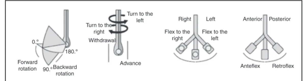
0.º 180.º 90.º Forward rotation Backward rotation Advance Turn to the
right Withdrawal
Turn to the
left Right Left Anterior
Anteflex Retroflex Posterior
Flex to the right
Flex to the left
Figure2 Probeandtransducerhandlingmovementstoacquireechocardiographicimages.AdaptedfromGalhardoetal.6
Table2 Transesophagealechocardiographycomplications.
Airwayandesophagusdirecttrauma
Esophagealbleeding
Esophagealburn
Dysphagia Bacteremia
Vocalcordparalysis
Indirecteffects
Hemodynamicandpulmonarychanges
Inadvertentairwaymanagement
Distractionduringpatientcare
Ingroup2,we havecomplicationsindirectlyrelatedto TEE,whichinclude:hemodynamic,pulmonarychanges, air-waymanipulations,anddistractionduringpatientcare.8It isimportanttoleaveallanesthesiaworkstationand moni-toralarmsturnedon,astheTEEdevicemaybepositioned ina waythatmakesit difficult tosee allthe monitorsat once.Furthermore,duringexamination,theexaminermay becomeinattentivewiththepatientandattempttodosome echocardiographic imaging or make a diagnosis. Initially, echocardiographicexamination withasecond anesthesiol-ogistatsiteisimportantsothat,whileoneanesthesiologist performs the echocardiographic exam, the other helpsin theintensivecontrolofthepatient.1,9
Probe
passing
technique
Probe introduction should be performed withthe patient underanesthesiaaftertrachealintubation.1Probeshouldbe lubricatedwithproperTEEgel(usuallylidocainegelor inti-matelubricant),andthestomachmaybepreviouslyemptied toenhancetheimages.1
Probepassingisoftenachallenge.Thetechniqueconsists ofproper lubrication of theprobe,passing it throughthe posteriororopharynxandelevatingthemandiblewiththe lefthand.Passingitthroughtheupperesophageal sphinc-teristheprocedurecriticaltimeinwhichthemostserious complicationsmayoccur.Theprobeshouldprogresstoward theesophaguswithoutresistance.6Incaseofresistance,this usuallyoccursbecausetheprobe’stipislodgedinthe pyri-formsinus,epiglotticvallecula,posteriorpartofthetongue, oresophagealdiverticula.Theprobeshouldneverbeforced againstresistance,asitmayleadtocomplicationssuchas perforationandbleeding.1
Anothertechniquethat canbeusedistheprobe intro-ductionwiththehelpofalaryngoscope.Inthiscase, care shouldbetakenwiththehemodynamicstimulus triggered byasecondlaryngoscopy.1
The TEE examination allows intra- and extracardiac anatomicalanalysisofthegreatvesselsatthebase,analysis ofcongenitalheartdefects,andqualitativeandquantitative analysisofDopplerflow.1,3Acompleteintraoperative exam-ination notonly characterizes the patient’s hemodynamic profile but may lead tochanges in the surgical approach in up to25% of the exams,in which changes such asthe presenceof apatentforamenovale(PFO), leftatrial(LA) thrombi,or atheromaplaquesin theascending aorta(Asc Ao).8
Theexaminations mustberecorded onadigital media forfurtheranalysisandmedicalreport.Thus,itispossible toanalyzethepatient’sevolutionbothintraoperativelyand postoperatively.6
Management
of
TEE
probe
The correct use of the multiplane TEE probe functions provides adequate acquisition of cardiac images during intraoperative examination. In addition, its proper han-dling reduces the incidence of stomach and esophageal complications.
Moving the probe in the caudal and cranial direction produces changes in the images in the inferiorand supe-riordirectionsof theheart, respectively (highesophagus: about20---25cm;mediumesophagus:about30---40cm; trans-gastric (TG):about 40---45cm;deepTG: about 45---50cm). Changestotherightorleftoftheheartcanbeobtainedby movingtheprobeclockwiseorcounterclockwise.Thebest alignmentoftheimagescanbeobtainedwiththeanterior or posterior movement ofthe probe, usinganteflexionor retroflexionwiththehelpofthelargerprobehandle.1 Multi-planeTEEprovidesfineadjustmentsintheinclinationangle oftheimageplane andconsequently allowsfor more pre-cise anatomicalanalysis. The angle mayrangefrom0◦ to 180◦ (Fig.2).1
Comprehensive
echocardiographic
examination
(LV),rightventricle(RV),andLVOTwithpartoftheAV.The evaluationof regionalLVfunction isimpaired bytheapex shortening(Fig.3A).
Mid-esophagealfour-chambercross-section
Advance the probe from the previous position (five-chamber)upto30---35cm.We candescribetheLV,RV,LA, RA,interatrialseptum(IAS),MV, andtricuspidvalve(TV). Thetrue(notshortened)apexmaybeexposedby retroflex-ingtheprobe.Itisoneofthemostusedviewsfordiagnosis (Fig.3B).
Mid-esophagealmitralcommissuralcross-section
Fromthepreviousposition(four-chamber),rotatetheprobe upto45---60◦.TheMVhasatypicalappearanceinthisimage (segments P1---A2---P3), the section passes through the MV
commissuralaxis.Papillarymusclesandchordaetendineae are identified. Small manipulations of the probe in this imagemayprovideanatomicaldetailsandamorecomplete analysisoftheMV(Fig.3C).
Mid-esophagealtwo-chambercross-section
Fromthecommissuralview, rotatetheangle between60◦ and 90◦. LA, left atrial appendage (LAA), LV,and MV are identified.Theanteriorandinferiorwallsareexposedand bothventricularandmitralvalvefunctioncanbeevaluated. Coronary venous sinus (CS) is seen onthe shortaxis, just abovetheLVbasalinferiorwall(Fig.3D).
Mid-esophageallongaxiscross-section
Inthetwo-chamberwindow,rotatetheangleto120◦.LA,LV, LVOT,AV,proximalAscAo,CS,andMV(P2andA2segments)
arevisualized.Adjustmentsaremadetomaximizeand accu-ratelymeasuretheLVOTdiameter.TheLVanteroseptaland inferolateralmovementscanbeinvestigated(Fig.4A). Mid-esophagealaorticvalvelong-axiscross-section
The probe is retracted a few centimeters fromthe posi-tionofthelongaxis inthemid-esophagus.Maintainingan angle of120---140◦,the LVOT, AV,andproximalAscAo are alignedand,fromthispoint,AVcanbeevaluatedandthe sinotubularandannulardiametersofAomeasured.Finding
Upperesophagealascendingaortashortaxis cross-section
FromtheAVlong axisview(120---140◦),theprobeis with-drawnand,with90◦counterclockwiserotation,theimages of Asc Ao short axis and superior vena cava (SVC) are obtained.Themainpulmonaryarterycanbeseenwith bifur-cation(proberotationtotheleft)andtherightpulmonary arterybranchcanbeseentoalargeextent(proberotation totheright).Itisagoodwindowtocheckpulmonaryartery catheterplacement(Fig.4D).
Mid-esophagealrightpulmonaryveincross-section
Fromtheprevious position(Asc Aoshortaxis) retractthe probebetween0◦and60◦androtateitclockwise.Theright upperpulmonaryvein(RUPV)andtherightlowerpulmonary vein(RLPV)arevisualized.The RUPVisshownwithaflow paralleltotheUS beamandcanbe evaluatedonDoppler mode.Occasionally,arightmiddlelobarpulmonaryveincan beviewedenteringtheLAbetweentheRUPVandRLPV ori-fices.Theevaluationofpulmonaryveinsisofspecialinterest incongenitaldiseases.
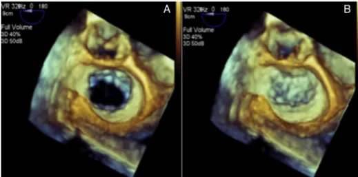
Mid-esophagealaorticvalveshortaxis cross-section
Fromthepreviouslydescribedview(rightpulmonaryvein) returntotheAointhescreen centerwitha counterclock-wise rotation of the probe. Advance to AV commissural leafletsat anapproximateangle of45◦.Thegeneral mor-phologyofAV(numberofvalves,presenceofcalcifications, motion)is observed, besides determiningif thereis pres-ence of aortic stenosis by planimetry. Interatrial septum (IAS)bulgingcontinuouslyinthecardiaccyclebyhigh pres-surescanalsobeobservedinthis window(Fig.5A).From thisposition, the discreet withdrawal of the probe or its anteflexionalsodepictstheLAA.
Mid-esophagealrightventricleinflow-outflow cross-section
Figure3 (A)Mid-esophageal five-chambercross-section. (B)Mid-esophageal four-chamber cross-section. (C) Mid-esophageal commissuralcross-section.(D)Mid-esophagealtwo-chambercross-section.
Figure5 (A)Mid-esophagealaorticvalveshortaxiscross-section.(B)Mid-esophagealrightventricleinflow-outflowcross-section. (C)Mid-esophagealmodifiedbicavalcross-section.(D)Mid-esophagealbicavalcross-section.
when compared to the visualization of four chambers in themid-esophagusplaneforflowanalysisbyTVonDoppler mode.Thiswindowisalsousefulincongenitalheartdiseases andinthecorrectplacementofpulmonaryarterycatheter (Fig.5B).
Mid-esophagealmodifiedbicavalcross-section
FromtheRVITandRVOTwindow,withaclockwiserotation between50◦ and70◦,TViscentralizedandLA,IAS,RAand inferior vena cava (IVC)are visualized. It maybe an api-calwindowtoanalyzeeccentricregurgitantjetsbyTVon Dopplermode(Fig.5C).
Mid-esophagealbicavalcross-section
From the window previously described (modified bicaval) raisetheangularrotationto90---110◦ androtatetheprobe clockwise. Structurestobe analyzed include LA,IAS, RA, SVC, IVC,and right atrial appendage (RAA).This visibility positionisespeciallyimportantforanalysisofPFOandIAS defectsandtodetectairwithintheatria,aswellastoassist inthedifficultpassageofthepulmonaryarterycatheterinto theRV(Fig.5D).
Mid-esophagealrightandleftpulmonaryveins cross-section
Inthebicavalpositioninthemid-esophagus(90---110◦) con-tinue to rotate the probe clockwise untilthe right upper pulmonary vein (RUPV) and right lower pulmonary vein
(RLPV) are visualized. When rotating the probe counter-clockwise,theRUPVandRLPVcanbevisualizedattheright endofthescreen,wheretheyarealignedparalleltotheUS soundbeam.Itis idealfor flow analysisonDopplermode (Fig.6A).
Mid-esophagealleftatrialappendagecross-section
Thiscross-sectionalviewisobtainedinthemid-esophagus with an angle between 90◦ and 110◦, turning the probe clockwise.The upper leftpulmonary vein(ULPV) is often visualized.Duetothecomplexandvariableanatomyofthe LAA,itsevaluationmustbedoneindifferentsections.Color DopplerandpulsatileDopplerareusefulmodalitiesof eval-uation,particularlyregardingtheLAAcontractilefunction (Fig.6B).
Transgastricbasalshortaxiscross-section
Figure6 (A) Upper-esophagealright andleft pulmonaryveinscross-section. (B)Mid-esophageal leftatrial appendage cross-section.(C)Transgastricbasalshortaxiscross-section.(D)Transgastricmid-papillaryshortaxiscross-section.
Transgastricmid-papillaryshortaxiscross-section
FromTG basal short axis cross-section, the probe should returntotheneutralposition, or beminimallyadvanced, maintaining the zero angulation. This cross-section is extremelyusefulinassessingandmonitoringthevolumeand sizeof regional andglobal LV function, aswell as assess-ingterritoriesirrigatedbytherightcoronary(RC),anterior descending (AD), and circumflex (Cx) arteries. In it, the anterior, inferior, inferolateral, anterolateral, and septal wallscanbeidentified,aswellasthepapillaryanterolateral andposteromedialmuscles(Fig.6D).
Transgastricapicalshortaxiscross-section
Maintaining contact with the gastric wall, the probe is slightly advanced and/or retroflexed from the TG mid-papillaryshortaxis,favoringthevisualizationoftheapical segmentsof the LVandRV (turning theprobeclockwise). Thiscross-sectionmaybedifficulttoobtainduetothe pos-siblelossofcontactbetweentheprobeandthegastricwall causedbyretroflexionoftheprobe(Fig.7A).
Transgastricrightventricularcross-section
ThisimageisobtainedatthesamelevelastheTGbasalshort axiscross-section,onlyturning theprobeclockwise.TVis visualizedonitsshortaxis.TheuseofcolorDopplerinthis cross-sectionmay helptocharacterize the TVregurgitant orifice(Fig.7B).
Transgastricrightventricularinflow-outflow cross-section
Thisimageisorthogonaltothatdescribedpreviously(simply rotatethetransducerby90◦).TheanteriorandposteriorTV cuspsandleftandrightPVvalvesareusuallyvisualized.This cross-sectioncanbeusedtoalignthejetsinPVwiththeUS beamforuseinthecontinuousandpulsatileDopplermodes (Fig.7C).
Deeptransgastricfive-chambercross-section
This image is obtained by advancing the probe in the stomach,maintainingcontactwiththegastricwall(probe anteflexion).ItistheidealincidenceforDoppleranalysisof AV,LVOT,andoftenMV, asbloodflow isparalleltotheUS beam(Fig.7D).
Transgastrictwo-chambercross-section
This cross-sectionis obtained fromTG mid-papillaryshort axis,changingtheangleto90◦.Itallowsevaluationofthe LVanteriorandinferiorwalls, aswell asthe entiremitral valveapparatus(MV,papillarymuscles,chordaetendineae). ItisalsopossibletovisualizetheLAandtheLAA(Fig.8A). Transgastriclongaxiscross-section
Figure7 (A)Transgastricapicalshortaxiscross-section.(B)Transgastricbasalrightventriclecross-section.(C)Transgastricright ventricleinflow-outflowcross-section.(D)Deeptransgastriccross-section.
arevisualized.BecauseLVOTandAVareparalleltotheUS beam,aDoppleranalysisispossible(Fig.8B).
Descendingaortalongandshortaxescross-section
Becausethedescendingaorta(DescAo)isadjacenttothe esophagusandstomach,theacquisitionofimagesissimple. FromTGmid-papillary shortaxis cross-section, theprobe shouldbe rotated at about 180◦, withslight adjustments untiltheabdominalAo(belowthediaphragm)isvisualized, attheceliactrunklevel;theprobeisdrawnandthe trans-ducerangleismaintainedatzerodegreeandtheshortaxis isobtained; thelong axis is obtainedwiththe transducer angle at 90◦. Image qualitycan be improved by decreas-ingthedepthandadjustingthegain.Becausethereareno internalanatomicalstructures inDescAo, thedescription of findingslocation is usually basedon thedistance from thefindingtothe incisorteeth.Anotherimportant factor intheDescAoevaluationisthehemiazygosveinpresence, whichdrains the posterior leftthorax,often visualized in themostdistalfieldoftheimage,joiningtheupperthorax totheazygosvein,whichdrainstherightthorax.The azy-gosvein,beingnormallyparalleltoAoanditswalls being contiguous,canoftenbeerroneouslyidentifiedasa dissect-ingaorticblade.ColorandpulsatileDoppleranalysiseasily differentiatesthearterialfromthevenousflow(Fig.8Cand D).
Upperesophagealaorticarchlongaxis cross-section
ThisimageisobtainedfromtheDescAoshortthoracicaxis; theprobeiswithdrawnuntilAobecomeselongatedandthe leftsubclavianarteryemergenceisvisualized.Thisposition indicates the end of the distal aortic arch. The probe is turned clockwise and it is possible tovisualize the mean aorticarchandtheleftinnominatevein.Becausetheleft sourcebronchusinterposesbetweentheesophagusandAo, itisusuallynotpossibletovisualizetheproximalaorticarch andthedistalAscAo(Fig.9A).
Upperesophagealaorticarchshortaxis cross-section
From the cross-section described above, the transducer angleisincreasedtoabout70---90◦toobtainthelongaxis. ThepulmonaryarterytrunkandPVcanbevisualizedonthe long axis; it is possible toobtain Doppler measurements. Dueto Ao curvature, the right brachiocephalic trunk and leftcommoncarotidarterycanoften beidentifiedtothe rightonthemonitor(Fig.9B).
Mitral
valve
Introduction
Among the cardiac valves, MV has the most favorable anatomiccharacteristics for transesophagealexamination, asthenearfieldisclosetothetransducer,hastheLAasan ‘‘acousticwindow’’,andhasnocardiacstructurethatcan
becalcifiedand/orgenerationofacousticshadowbetween thetransduceranditsstructure11(Fig.1).
DuringtheMVintraoperativeperiod,TEEisa fundamen-taltool,asitallowsthelesionidentificationandadetailed descriptionofitsmechanismandseverity,thushelpingthe surgicaldecisionmaking.11
Anatomyandnomenclature
WhenstudyingtheMVanatomyandfunction,themost cor-rect is that it is viewedas a valvecomplex composed of distinct anatomical structuresthat work in a coordinated wayforitscorrectfunctioning.12Themitralvalvecomplex, or mitralvalve apparatus, iscomposed of mitralannulus, cusps, chordae tendineae,papillarymuscles, and theleft ventricularmusculature.12
Mitralannulus
The mitralannulusis aconnectivetissuestructure witha three-dimensional saddle-shaped complex structure. It is anteriorly relatedtotheaortic valveapparatus, joinsthe atriumandleftventricle,andreceivesalongitsperimeter theinsertionofthevalvularcusps.12
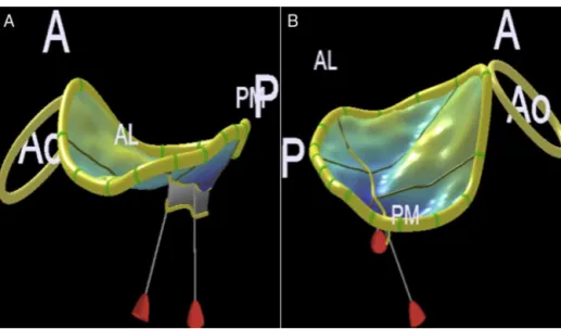
Mitralannulus has twomain axes,one anteroposterior (upperandshorter)andonecommissural(lowerandlonger). Theseaxesmayalsobereferredtoasanteroposteriorand anterolateral---posteromedial13(Fig.10AandB).
Under the ventricular contraction action, the mitral annulus posteriorregion undergoes asignificant reduction ofitstotalarea,withreductionupto25%.Themitral annu-lusanteriorregionfoldsduringsystoleandfurtherdecreases theanteroposteriordiameter.13
Leaflets
(cusps)
The normal mitral valve complex is composed of two anterior and posterior leaflets.12,13 The anterior leaflet is inserted into the anterior annulus, in a fibrous skele-ton region adjacent tothe aortic valve apparatus, called mitral-aortic intervalvular fibrosa (MAIVF). It occupies approximately 1/3 of the annular perimeter and 2/3 of its area. The posterior leaflet inserts into the posterior annulusandoccupies2/3ofitsperimeter,butcorresponds to only 1/3 of the annular area.13,14 The leaflets are in a curved coaptation line along the intercommissural axis (anterolateral---posteromedial); innormal situations,there areapproximately1cmoftissueoverlap.12
MV leaflets were subdivided into distinct regions in ordertoimprovecommunicationamongmedicalteam mem-bers.Amongtheproposedschemes,wewilluseCarpentier nomenclature,10 whichisalsousedbyASEandSCA.1
Figure9 (A)Upper-esophagealaorticarchlongaxiscross-section.(B)Upper-esophagealaorticarchshortaxiscross-section.
Figure 10 Mitral annulus assessment by three-dimensional echocardiography. (A) Anteroposterior diameter. (B) Anterolateral---posteromedialdiameter.Ao,aorticring;A,anterior;P,posterior;AL,anterolateral;PM,posteromedial.
anteriorregion(A1),amiddle region(A2),andaposterior region(A3).At theanterolateral and posteromedialends, two regions are defined as anterolateral commissure and posteromedialcommissure,respectively10(Fig.11).
Papillarymuscles,chordae tendineae,andleft ventricle
The two papillary muscles (anterolateral and posterome-dial)supporttheleaflets,locatedparalleltotheventricular musculature.12 The anterolateral muscle generally arises from the middle portion of the anterolateral LV wall, receivesvascularizationfromtheADandCxarterybranches. Theposteromedialpapillarymusclearisesfromthemiddle portionof theinferior wall,is exclusively vascularizedby the RCartery branch,which makesit more vulnerableto ischemicinsult.12
Thechordaetendineaeconnectboththepapillary mus-cles and ventricular musculature to the MV leaflets. The anterolateralpapillarymusclesupports,throughitscords, the A1/P1 segments and the anterolateral portionof the A2/P2 segments; the A2/P2 posteromedial portion and
the A3/P3 segments are supported by the posteromedial papillary12(Fig.12).
Chordae tendineae are classically divided into first, second and third-order chordae. First-order chordae are connectedtothetipoftheleaflets,havingasaconsequence ofitsrupturethesystoliceversionofleaflets, echocardio-graphically known as flail.12,13 Second-order chordae are connectedtothebase ofleafletsandareknownas struc-turalchordae;itispossibletoidentifytwotofourchordae thickerthantheothers.12,13Third-orderchordaeusually con-nect the posterior MV leaflet to the left ventricle wall, havingrecognizedimportanceinarchitecturemaintenance andventricularperformance12 (Fig.12).
Intraoperativemitralvalveechocardiographic examination
Figure11 Carpentiernomenclature:segments#1are antero-lateral,#3areposteromedial,and#2correspondtothevalve mid-portion.The anteriorandposteriorcommissuresarealso visualized.12
Figure12 Mitralsubvalvarapparatus,showing thechordae tendineaedistributionateachcusp.12
ofimageacquisitionandtrainingwerealsoadoptedbythe SBAforteachingandtraining.4
Didactically,wewilldescribetheMVsequential evalua-tionmethodthroughtheASE/ACS methodology,1 trying to identify its different segments according to their clinical importance.It is known that its accuracy is variableand highlydependentontheexaminer’sexperience,as demon-stratedbyMahmoodetal.16 Ontheotherhand,theability tolocalizeitspatiallyinthemitralapparatusanatomyusing two-dimensional(2D)examinationstillrequires fundamen-taltraining.
Mid-esophagealfive-chambercross-section
Withtheprobeinsertionatadepthofapproximately30cm, with multiplane angle rotation about 10◦, AV, LVOT, LV (exceptitsapex),andA1---A2andP1---P2segmentsare visu-alized(Fig.3A).
Mid-esophagealfour-chambercross-section
The probe is insertedat a depth of approximately35cm, withmultiplaneanglerotationbetween10◦ and20◦,until MVcanbeclearlyvisualized.ThesegmentsA3---A2andP2---P1 areevident,aswellastheTVseptalandposteriorleaflets (Fig.3B).
Mid-esophagealcommissuralcross-section
With the probe in the four-chamber position, the multi-planar angle is advanced between 50◦ and 70◦ and the commissuralplanewillbevisualized.ThesegmentsP1,A2, and P3 will be visible from right to left, in addition to thepapillaryanterolateralandposteromedialmuscles.The probeisrotatedtotherightandtheimageplanewillpass throughthe entire extensionof the anteriorleaflet(right commissural:A1---A2---A3),aswellastheentireextensionof theposteriorleafletwhenrotatedtotheleft(left commis-sural:P1---P2---P3,Fig.3C).
Mid-esophagealtwo-chambercross-section
From the commissural plane, the multiplane angle is advancedbetween80◦and100◦andtheimageplanecalled two-chamber willappear. Fromright toleft,the MV seg-mentswillbeA1/A2/A3andP3(Figs.3Dand4A).
Transgastricbasalshortaxiscross-section
Thetransducer isadvancedtothestomach,withthe mul-tiplane angle between zero and 20◦, and a MV image is obtainedwithafishmouthopeningandclosing.The ante-riorleafletappearstotheleftandtheposteriorleafletto theright;theposteromedialcommissureappearsnearthe transducerandtheanterolateralcommissuremoredistalto thetransducer(Fig.6C).
Three-dimensionalfrontalcross-section(faceview) MV apparatus 3D evaluation is useful for defining and locating the pathology, describing the pathophysiological mechanismanditsseverity,aswellasfacilitating communi-cationwiththeinterventionalsurgeonorcardiologist.1With the evolution of surgical and percutaneous techniques of mitralapparatusrepairtherewasaneedforreal-timehigh qualityimages,whichisnowpossiblethankstothe techno-logicalevolutionofthematrixarrayandimagemanipulation softwares.17
Thecomplete3Dexaminationwillbetreatedinaspecific topic, but we will describe twomore representative and usefulintraoperativeimagingplans,whichmaybein real-timeorinmulti-beatacquisitions.
Leftatriumvieworsurgeon’sview
FromtheLAview,itispossibletoidentifyallthevalve seg-mentation,whichfacilitatesthetopographicdescriptionof apathologyandcommunicationwiththesurgicalteam.By convention,AVispositionedat12o’clockintheimageand LAAat9o’clock(Fig.13AandB).
Leftventricleview
Figure13 Mitralvalveviewinthree-dimensionalimage.(A)Mitralvalveindiastole.(B)Mitralvalveinsystole.
Figure14 Mitralvalveviewofleftventricleinthree-dimensionalimage.(A)Mitralvalveindiastole.(B)Mitralvalveinsystole.
atthetop,anterolateralcommissuretotheright,and pos-teromedialcommissuretotheleft(Fig.14AandB). 3DcolorDopplerechocardiography
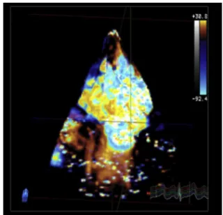
Bymeansofmulti-beatacquisition,itispossibletoobtain volumetric images of the regurgitant jet and its relation withtheMVstructuresand3Devaluationofitsvarious com-ponents,whichallowstodemarcateitsexactlocationand quantitativeevaluationinspecificsoftware18(Fig.15). Three-dimensionalquantitativeevaluationofmitral valve
Besidestheabilitytogeneraterealtime3Dimages, numer-oussoftwareweredevelopedwiththeabilitytogeneratea quantitativeanalysismodelfromspecificpointsmarkedon the3Dimageofthevalveapparatus.Amongthese,themost widely used and studied software are Mitral Valve Quan-tification --- MVQ (PhillipsHealthcare®, Inc.,Andover, MA) and4DMV---AssessmentSoftware(TomTecImagingSystems GmbH®,Munich,Germany).18Althoughreferencevaluesand clinical usefulnessarestillin thevalidationstage, impor-tant knowledge has been accumulated regarding mitral valveapparatusremodelingindifferentpathophysiological states.18
Intraoperativeevaluationofmitralvalve
The evaluation objectives beforecardiopulmonary bypass aretodefinethemechanism,locatethelesion,estimateits severity,and identifyassociatedpathologies, suchas pul-monaryarterialhypertension,ventriculardysfunction,and tricuspidregurgitation.13 Itshouldbenoted,however,that generalanesthesiasignificantlymodifiesthehemodynamic conditionsandoften decreasestheseverityof regurgitant valvelesions.13
Evaluationofannularmorphology
Figure15 Three-dimensionalcolorDopplerofmitralvalve.
Leafletsevaluation
MV diseases can be classified according to the leaflets motion,accordingtoCarpentier’sclassification.10,19
DiseasesareclassifiedastypeIifpresentingwithnormal leaflet motion, such as mitralregurgitation due to endo-carditisleadingtoleaflet perforation,congenitalcleftsor isolatedannular dilatation, in case of atrial fibrillation19; type II if presenting with excessive leaflet motion, such as prolapse caused by fibroelastic deficiency or Barlow’s disease19;andtypeIIIwhenpresentingwitha pathophysio-logicalmechanismthatcausesrestrictedleafletmotionand maybesubdividedintoIIIa,IIIb,andIIIc.The IIIasubtype correspondstorestrictioncausedbyshorteningandfusionof thesubvalvarapparatus,suchasinrheumaticheartdisease. TheIIIbandIIIcsubtypesrepresentrestrictionduetoleaflet tethering,asinfunctionalmitralregurgitation,withIIIb cor-respondingtosymmetricandIIIctoasymmetrictethering19 (Fig.16BandC).
MitralregurgitationcausedbytypeIIpathologiesin gen-eral produceregurgitant jetsin the opposite direction of thelesion;however,centraljetsmayoccurincaseofboth leafletsinvolvement.19
Type III pathologies, with restricted leaflet motion, usually produce regurgitant jets in the same direction as the leaflets, may be central in case of symmetrical involvement.19
Systolicanteriormotion
Systolicanteriormotion(SAM)ofMVhasbeenreportedafter valverepair,withan incidenceupto16%in patientswith myxomatousdisease.20 Itconsistsoftheanterior displace-mentofthecoaptationpointandsubvalvulartissuetoward LVOT during systole, causes varying degrees of dynamic obstruction20(Fig.17).
Notall SAM causesclinically relevant obstruction. It is traditionallydiagnosedinthepresenceofagradientacross theLVOTandmitralinsufficiency.20 Thepresenceofmitral tissueacrosstheLVOTis oftenpossibletobeverified,but withoutanygradient,asituationclarifiedby3D/4DTEE.14 Theabilitytoechocardiographicallypredictwhichpatients areatgreatestriskforSAMdevelopmentaftermitralrepair isakeytaskofintraoperativeexamination.Inthelasttwo decades,somecriteriahavebeendefinedandvalidated.The mostrelevantonesarethefollowing:20---22
• Distance between coaptation point and septum (5-chamberlongaxis)<2.5cm;
• Posterior leaflet systolic length (5-chamber long axis) >1.5cm;
• Relationship between anterior/posterior systolic length (5-chamberlongaxis)<1.4cm;
• Smallventricularcavity---diastolicdiameter<4.5cm; • Interventricularseptum(IVS)bulging>1.5cm;
• Mitroaorticangle(3Dquantification)>65◦atrestand>35◦ understress;
• Aortomitralangle(3Dquantification)<120◦.
Figure17 Mitralvalveanteriorsystolicmotion.
Junction Sinotubular
Aortic ring
LVOT
Ascending
aorta
RVOT
LV
Figure18 Aorticcomplex.LV,leftventricle;LVOT,left ven-tricularoutflowtract;RVOT,rightventricularoutflowtract.
Leftventricularoutflowtract,aorticvalveand aorta
AVis a component ofthe aortic root, whichby definition extends from the basal aortic valve annulus to the sino-tubularjunction.WiththeassociationoftheLVOTinterval triangles,wewillhavetheso-calledaorticvalvecomplex23 (Fig. 18). Pathologies can occur not only in AV but also involveanycomponentsof thiscomplex,whichreinforces theimportanceofadetailed,hemodynamic,andanatomical evaluationofthisregion.1Withtheadventofnew technolo-gies for treating aortic complex pathologies, therewas a greatadvanceintheunderstandingofitsanatomy;2Dand 3DDTEEstandoutinthedetailedmorphologicalevaluation oftheseanatomicalstructures.24
Anatomy
TheaorticvalvarcomplexisacontinuationoftheLVOTandis locatedtotherightandposteriortotheRVOT,withits poste-riormarginwedgedbetweenMVorificeandmuscularIVS.24 Itsbasalcircumferenceiscalledaorticannulusorbasalring (Fig. 18) and has an oval shape in most individuals.24---26
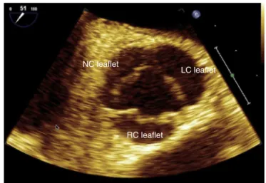
Figure 19 Mid-esophageal aortic valve short axis cross-section.NC,non-coronary;LC,leftcoronary;RC,rightcoronary.
Approximatelytwothirdsof thisbasal ring,where the AV valvesnadirsareinserted, areconnectedtothemuscular IVS and the remaining third is in contact with the mitral valveanteriorleaflet,representsthebaseofafibrous tri-angle between the non-coronary valves and left coronary artery(‘‘fima’’).
The aortic root extends from the aortic valves basal insertiontothesinotubularjunction,passesthroughthe Val-salvasinuses,fromwhere onthe upperborderofthe left andright coronarysinusesthecoronaryarteriesoriginate. Thus,AVis asemilunarvalvewiththreevalves,identified accordingtothepresenceorabsenceofacoronaryartery, whichoriginatesfromthecorrespondingsinus ofValsalva: leftcoronaryvalve,rightcoronaryvalve,andnon-coronary valve24(Fig.19).
2DandDopplerimagingofaorticvalveandleft ventricularoutflowtract
ItsanatomicallocationclosetotheLA,whichisincontact with the esophagus in its mid-plane, provides a precise anatomicalimage,bothinshort(Fig.5A)andlongaxesviews (Fig.4B).24TheperpendicularcontactoftheUSbeamswith thesenearfieldallowsustousethehighestavailable fre-quencies, with consequent detailed appreciation of their morphology.5 The use of zoom as a resource to increase thedetailfordistanceand/ordiametersmeasurementscan further improve accuracy and is recommended (Fig. 20). TheDopplerbundlesperpendicularitywiththesestructures inthe mid-esophagusechocardiographic sectionsmakesit impossibletoaccuratelyassesstheflowvelocities.5This lim-itationisovercomewithTGlongaxis(Fig.8B)anddeepTG sections(Fig.7D),inwhichtheparallelalignmentwiththe beamsallowsanaccurateassessement.5,27
Mid-esophagealaorticvalveshortaxis cross-section
LVO
T
Asc Ao
IVS
(basal)
RC leaflet
LVOT Diam 1.7 cm
2.27 cm2 Area
LVOT
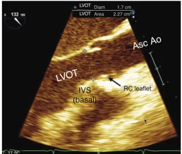
Figure 20 Mid-esophageal aortic valve long axis cross-section.LVOT,leftventricularoutflowtract;IVS, interventric-ularseptum;RC,rightcoronary;AscAo,ascendingaorta.
themostanteriorposition,non-coronaryvalveadjacentto theIAS,andleftcoronarycusppositionedlaterallytothe left(Fig.19).This cross-sectionpresentsexcellentspatial and temporal resolution, allowing a detailed view of the valveshapeand function, which is important toevaluate thevalvardysfunctionmechanisms.ColorDoppler flowme-try is applied to assess aortic regurgitation and the size, mechanism,andpositionoftheregurgitantorifice.28Probe removaloranteflexioncandisplaytheleftcoronaryostium image,aswellasitsintroductionorretroflexioncanprovide animageoftheLVOTshortaxis.
Mid-esophageallongaxiscross-section
The multiplane angle is rotated to 120◦, from the mid-esophagial four-chamber cross-section, and the basal portionofIVS,LVOT,aorticroot(aorticring,Valsalvasinus, andsinotubularjunction),andAscAoproximaltubular por-tionappearsontheright sideofthe image(Fig.20).Two AVvalvesare displayed,theright coronary isalways that mostdistaltothetransducerbecauseitis themost ante-rior.Theothercusppresentinthiscross-sectionmaybethe leftcoronary, or most often the non-coronary, depending onthe commissure positionbetween them and the exact locationof theimagingplate asit passes throughthe AV. Presenceof calcification, thickening, motion degree, and valveopening, aswell asitsanatomical relationship with adjacentstructures,suchascoronaryostiaandIVS,should beevaluated.Thebasalaorticringdiametermeasurement ismadeinthiscross-sectionusing2DTEE,preferablywith zoomimage, as the distance between the most ventricu-lar nadir of the right coronary valveand the base of the fibroustriangle(‘‘fima’’),contralateraland orthogonalto theaorticrootlongitudinalaxis,intheventricularsystole. Thismeasureisusuallysmallerthanthatofthecoronalaxis (onlyobtainedvia3DTEEortomography)duetothebasal ringovalshape. Thisevaluation accuracy isimportant for
hemodynamic measures of systolic volume and cardiac output,aswellasforpredictingthesizeof aortic, percu-taneous, or surgical prosthesesplaced in this region.27 In addition,thediametersoftheothercomponentsofthe aor-tic root, as well asthat of Asc Ao, should be measured. In case of aortic stenosis, where there is proximal flow convergence, the LVOT diameter (located approximately 5mmbeforetheaorticring)shouldbeused---pulsed-Doppler sample volumeis placedinthesame sitetocalculate the systolicvolumeejection.29Inthiscross-section,the perpen-dicularityoftheUSbeamincidenceinthisregionflowdoes not allow accurate velocity measurements with pulsatile and/or continuous Doppler.28 In contrast, color Doppler measurements are useful and reliable, providing impor-tantinformation,suchas:turbulentflowregionswithLVOT obstructions; measurement of vena contracta regurgitant jet;andrelationbetweenregurgitantjetdiameterandLVOT diameter.28
Transgastriclongaxisanddeeptransgastric cross-sections
Thesecross-sectionsareessentialintheassessment, allow-ingaccuratealignmentofLVOTandAVflows,withreliable measurement of their velocities through continuous and pulsed Doppler modes, important for gradation of valvar and/orsubvalvularstenoses,regurgitantjets,and measure-mentofLVejectedsystolicvolume(Figs.7Dand8B).27,28
Inthiscross-section,evaluationsofanatomicalstructures lose spatial resolution because theyare distant from the focus and parallel to the US bundle, the complementary action of trangastriccross-sectionswithmid-oresophageal cross-sectionsisemphasizedinthecompleteassessmentof AVandLVOTandmeasurementofejectionsystolicvolume andcardiacoutput.
2DimagingandDopplerofascendingaorta
esophagus, the aortic arch appears in longitudinal view, due to its anatomical position at that level (Fig. 9A). If inthisplanetheangleisturnedtoapproximately90◦,the leftsubclavianarteryexitcanbeevaluateand,turningthe probe tothe left, part of itsextension can be evaluated (Fig.9B).Withananti-clockwiserotation,thetwoother bra-chiocephalicvesselscanbeevaluate.Theinnominateartery viewisthemostdifficultbecauseitislocatedinablindspot wherethetracheainterposes.34 Theuse ofX-plane, avail-able in 3D transducers,allows thethoracic Ao evaluation in both longitudinal andtransverse planessimultaneously, improvesthetimeneededforevaluation,andgeneratesan
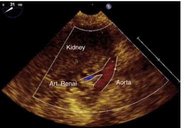
Kidney
Art. Renal Aorta
Figure21 Renalarterycross-section.
Atherosclerotic plaques
Figure22 Atheromaplaquesindescendingaortashortaxis.
positiondefinition.
3Dimagingofaorticvalveandaorta
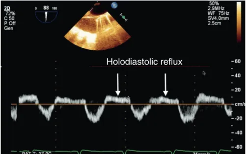
Holodiastolic reflux
Figure23 PulsedDopplerindescendingaortashowingaholodiastolicrefluxofsevereaorticregurgitation.
Volumetric capture
Figure 24 Three-dimensional volumetric analysis of aortic valve.
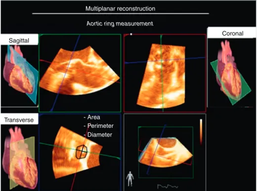
theoutcomeoftheseprocedures,asfarastwo-year mor-talityisconcerned,46,47andcouldonlybemeasuredwith3D images(Fig.26),sincecalculationsusingthemathematical formulasof2Dechocardiographywereshown tobe signifi-cantlyinaccurate.26,48 The identification thatLVOT hasan ellipticalshapeinmostpatientsincreasedtheimportance of 3D TEE due tothe inability of 2D echocardiography to performthese important measurements accurately.26 The distantlocationfromthetransducerfocus,thedistal curva-ture,thethinthicknessoftheAVvalves,andtheartifacts resultingfromthereverberationandacousticshadowofthe existingcalcifications are some of the challenges for the acquisition of 3D echocardiographic imaging of the aortic root.26ColorDoppler3Dshouldalsobeusedtoevaluate nor-malflowandabnormalities,allowtwo-dimensionalcutswith perfectspatialorientation,andtheoddanalysisofall abnor-malflow aspects,suchasmeasurement ofthe contracted veinarea,whichisimportanttoquantifytheseflows, with-outtheneedtoapplygeometricformulasthatareimprecise forthesituation.37
Pulmonary
valve
Anatomy
PVisathoracicanteriorstructurelocatedobliquelytothe plane oftheAV.49 It isasemilunarvalvecomprisingthree valves denominated by their positions relative to the AV (left,right,andanterior).49UnlikePV,thereisnocontinuity ofPVwiththecardiacfibrousskeletonorright atrioventricu-larvalve.49Becauseitsvalvesarethinandpoorlyechogenic and becauseit is far fromthe transesophageal probe,PV evaluationusingTEEisgenerallydifficult.1
2DandDopplermodes
RVOT,PV,andpulmonaryarterydimensionsarebest evalu-atedthroughthecross-sectionalviewofthemid-esophageal RVinflowandoutflowtracts,inwhichtheUSbeamis per-pendiculartothesestructures(Fig.5B).49Theanteriorvalve inthiscross-sectionistheonefurthestfromthetransducer, whereasthe oneclosest totheAVmay correspondtothe rightorleftvalve.Incaseswherethesesectionalviewisof poorquality,TGcross-sectionsoftheRVinflowandoutflow tracts, upper esophageal aortic arch shortaxis (Fig.9B), and mid-esophageal Asc Ao short and long axes (Fig. 4C and D) may be usedto supplement informationon struc-ture,dimensions,andfunctionofthepulmonaryvalveand artery.1
Transverse
Figure25 Three-dimensionalmultiplanarreconstructionofaorticvalve.
Sagittal
Coronal
Transverse
Multiplanar reconstruction
Aortic ring measurement
- Area - Perimeter - Diameter
Figure26 Multiplanarreconstructioninassessingaorticvalvearea.
3Dpulmonaryvalve
PV 3D images can be acquired on upper esophageal aor-ticarchshortaxisormid-esophagealaorticvalvelongaxis cross-sections after a slight rotation of the probe to the left.1,49
Multiplanar image
3G image
Figure27 Three-dimensionalimageofdescendingaortaatheroscleroticplaque.
Left
atrium
and
pulmonary
veins
Anatomy
Inrelationtotheribcage,theLAisthemostposterior cham-beroftheheart.Itislocatedveryclosetotheesophagus, separatedonlybythefibrouspericardium.51Trachea bifur-cation,esophagus,andDescAoareimmediatelybehindthe LAposteriorwall.ThisLAproximitytotheesophagusisvery advantageousforTEE,asLAisusedasawindowtoobtainthe mid-transesophagealviews.1,51 Intheseviews,LAisalways at thetop of the screen, closetothe US beam (Fig.1).1 InrelationtoRA,LAis moreposteriorandsuperiorandis separatedfromRAbyIAS.52
LAwallscanbedescribedassuperior,posterior,left lat-eral,septal(or medial),posterior---inferior,andanterior.53 LA anterior wall is behind the transverse sinus, that is, behindtheAoroot.CSgoesthroughtheposterior---inferior walloftheLA.LAwallsaremuscularanditsthicknessmay varyfrom1±0.5mm. Abnormal wallthickeningmay indi-catethepresenceofamuralthrombusorevenendocarditis. MitralannuluscalcificationmayextendtotheLAwalland makeitthicker.1,52
LAAisablindbottomstructurewithanaperturetoLA. InrelationtoLA,itis locatedlateralandsuperior andits tipisdirectedanteriorly, overlapspulmonary arterytrunk and left coronary artery.51 LAA has an average diameter of10---24mm, but thisvalue mayvary. Comparedto RAA, LAAhasanarrowerorificethatfacilitatestheformationof thrombiinsituationsoflowbloodflowandinnon-sinus car-diacrhythms.51BetweenLAAandULPVthereisatriangular foldoftheserouspericardiumcalledcoumadinridge,which whenprominent maybeconfusedwiththrombusor atrial mass(Fig.6B).
Accordingtotheblood flow,LAstartsatthevenoatrial junction and ends at the MV orifice. The four pulmonary veinsentertheposteriorpartoftheLA,theleftveinsare
locatedmoresuperiorthantherightveins.51Therearetwo right(RUPVandRLPV)andtwoleftpulmonaryveins(LUPV and LLPV). The RUPV passes behindthe RA junctionwith SVCandtheRLPVpassesbehindtheintercavalarea.52The right pulmonaryveinsorificesaredirectly adjacenttothe IAS plane. On the other hand, the left pulmonary veins arelocatedbetween LAAand DescAo, ULPVispositioned posteriorlysuperiortotheIAS,whereasLLPVispositioned posteriorlyinferior.52,54
Physiology
LAis notjustasimple blood-carryingcamera. Itresponds dynamically to its distention with the secretion of atrial natriureticpeptidesandparticipatesinthemanagementof bodyfluids.55LAalsofunctionsasabloodreservoirfromthe pulmonaryveinsduringventricularsystoleand isovolumet-ricrelaxation.Duringdiastole,LAworksasbloodconduitto LV.Attheendofdiastole,atrialsystoleoccurs,contributing with15---30%ofthevolumetransferredtoLV.56 BecauseLA is an LVcontinuumduringdiastole,changesin ventricular complianceaffectsthesizeandfunctionofLA.56,57
TheincreaseinLAisapredictorofcardiovascularadverse events, as well as the onset of atrial fibrillation, intrac-ardiac thrombi formation, and cerebrovascular accidents (Fig.28AandB).58Whenathromboembolicsourceis inves-tigated, LAA is the first site to be evaluated; TEE has a sensitivity and specificity for thrombus diagnosis of 100% and99%,respectively.However,becausetheyaresmalland complexstructures,theycan beleftundiagnosedin some circumstances.59
2D
and
Doppler
imaging
of
left
atrium
and
left
atrial
appendage
AV
RV
Figure28 (A)Echocardiographicimageofleftatriumthrombus.(B)Thrombus.LA,leftatrium;RA,rightatrium;AV,aorticvalve; RV,rightventricle.
• Mid-esophagealfour-chamber(Fig.3B); • Mid-esophagealcommissural(Fig.3C); • Mid-esophagealtwo-chamber(Fig.3D); • Mid-esophagealleftatrialappendage(Fig.6B); • Mid-esophageallongaxis(Fig.4A);
• Mid-esophagealaorticvalveshortaxis(Fig.5A); • Mid-esophagealbicaval(Fig.5D);
• Transgastrictwo-chamber(Fig.8A); • Deeptransgastric(Fig.7D).
Thecross-sectionalimagesthatmosteasilyevaluatethe LAarethemid-esophagealones.LAisthestructureclosest totheUSbundleinthemid-esophageal views;itisalways foundatthetopofthescreen.TEEcross-sectionsthat eval-uateMVwillnecessarilyevaluateLA.1
LA evaluation starts from the mid-esophageal four-chamber view (Fig. 3B). Rotate the angle, going through theotherviewstoobtain2Dcross-sections.Intwo-chamber view (Fig. 3D), LAA image should be increased (Fig. 6B) to better visualize the presence of thrombi, particularly in riskpatients. Inbicavalview, the relationshipbetween LA and IAS and RA is evaluated, looking for PFOand IAS defects. In these cross-sections, the pulmonary veins will also be evaluated, as will be discussed below. After the esophageal evaluation,the transducer is advancedto the TGcross-sections. At the 90◦ angle, LA andespeciallyMV anditssubvalvarapparatusareevaluated.IndeepTG cross-section (Fig. 7D),LAcan alsobevisualized, butthis view is more usedfor transaorticflow evaluation; LAis a sec-ondary evaluationbecauseit is furtheraway fromtheUS beam,withalowerresolutioncomparedtotransesophageal cross-sections.
DuetotheproximitybetweenLAandesophageal trans-ducer,LAcannotbeevaluatedinitsentiretybyasingleview, whichmakesitscomplete evaluationanditsdiameterand volumemeasurementsdifficultonTEE.1LAareaandvolume maybeunderestimated.Thelinearmeasurementsacquired onTEEinmid-esophageal aorticvalvelongandshortaxes viewsaretheonesthatbestcorrelatewiththeTEE paraster-nallongaxiscross-sectionalmeasurement,whichmeasures LAin theanterior-posteriorsense.60 In longitudinalsense, thevertexshouldbemeasuredfromsectortoAoroot,but thesemeasurementshavenonormalizedvalues. Septolat-eral measurements and LA volume can be obtained with mid-esophagealfour-andtwo-chambercross-sections. How-ever,thesemeasurements,althoughcorrelatedwiththose obtainedonTEE,havenonormalizedvalues.60
LAAevaluationmaybeinitiated withthefour-chamber cross-section, but because it is a lateral structure, the probeshouldberotatedcounterclockwise andanteflex to bringLAAtothe screen center.1 Alsoin thetwo-chamber cross-section, LAA site can be zoomed in or the screen depth be reduced to evaluate LAA more accurately. An organized thrombus is echocardiographically defined as a well-circumscribed mass of uniform consistency and a texturedifferentfromthatoftheatrialwall(Fig.28).1 Spon-taneouscontrastis notwellcircumscribed, hasadynamic localization, and appears as a ‘‘cigarette smoke’’ --- this imageiscausedbytheslowingdownofbloodflow(Fig.29).61 Inhigh-risk patients for LAA thrombus(atrial fibrillation), theriskofthrombusformationshouldbeassessedthrough the analysis of blood flow velocity.61 Pulmonary Doppler shouldbeplaced1---2cmfromLAAostium.Velocitieslower than27cm.s−1areassociatedwiththeformationof
LA
LV
RV
Figure29 Mid-esophagealfour-chamber cross-section showing rheumatic mitralstenosis. Note thepresence ofspontaneous contrastinleftatriumandmitralvalveleafletsthickening.LA,leftatrium;LV,leftventricle;RV,rightventricle.Source:Personal collection.Yellowarrowindicatesmitralstenosis.Redarrowindicates‘‘cigarettesmoke’’inleftatrium.
2DandDopplerimagingofpulmonaryveins
ULPVisthemosteasilyfoundbyTEE.WhenLAAisfoundin the60◦mid-esophagealplane,theprobeisgentlyremoved andULPVwillappearaboveandposterolateraltoLAAand tothecoumadinridge(anatomicvariantthatisoccasionally foundintheleftatrium)(Fig.6A).1
TheLLPVisthemostdifficultpulmonary veintoobtain onTEEimage.AftertheULPVimageisobtained,theangle is increasedto 90◦. The leftpulmonary veins will appear asaninvertedV-shape.ColoredDopplerissettoavelocity of40cm.s−1andlaminarbloodflowisobservedtowardthe
TEEtransducer.AnotherwaytoacquiretheLLPVimageis, afterfindingLAA,advancetheprobeandrotate itslightly clockwise and when LAA has disappeared, LLPV will be visible.1
RUPV is found with the mid-esophageal bicaval cross-section at 110---120◦, near the right pulmonary artery.63 The angulation is returnedto 90◦, andthe tworight pul-monary veins in inverted Y-shape can be evaluated. The rightpulmonaryveinscanbevisualizedatzerodegree mid-esophagealby rotating theprobe totheright so thatthe rightsideofLAliesinthecentralpartofthescreen.From thisposition,theangleisopenedto30◦andRUPVislocated totherightofthescreenandRLPVtotheleftofthescreen, enteringperpendiculartoLA.63
Toassessthebloodflowpatternofpulmonaryveins,apply pulsedDopplerwithavelocitylimitof40cm.s−1.Thenormal
flowpatternisthree-phasewithsystolic(S1 andS2), dias-tolic(D),andreverseatrial(A)waves.Diastolicdysfunction, mitraldiseases,andrhythmdisturbanceschangethisnormal pattern.1
Rightatrium,tricuspidvalveandvenous connections
RAistheheartcavitythatreceivessystemicvenousblood fromIVCandSVC,aswellasbloodreturningfromthe coro-naryarteriesthroughCS.Itsmedialandposteriorwallisthe IAS,thestructurethatseparatesitfromLA.Itsflooristhe TV, which opensinto theright ventricle.64 Seen from the rightside,IAShasacharacteristicstructure,anovalfossa, whichshowsoutwardcontourandcentralregionconstituted bya delicateblade.This blademostanteriorportionmay notbe completelyadhered totheovalfossa edge,theso calledPFO.65 Necropsystudiessuggestthatitispresent in upto27%ofadults.Itsinvivodiagnosisdependsondynamic evaluationwithmaneuversthatcauseincreasedRApressure concomitantwiththeinjectionofagitatedsalinesolution. Ahigherprevalencehasalsobeenassociatedwiththe pres-enceofIASaneurysm.65
TheLAlowerportionisseparatedfromLVbyaportionof fibroustissuethatcontinueswithIVS,calledfibrousseptum. This is due to the different levelsof implantation of the tricuspidand mitralvalves. TVhas moreapical insertion, whichresultsintheareaknownasatrioventricularseptum. CS outflow is located posteriorly and medially to the IVC ouflow next to the atrioventricular transition. In this region,remnantsofvenousvalvesmaybefound,withthe EustachiannexttoIVCandtheThebesianrelatedtoCS.64
mid-anteriorandinferiorportionsofIAS,correspondingto theovalfossaandseptumprimumregion.1
Fromthisposition,thetransducerisloweredtowardthe TGplanes,andtheangleismaintainedatzerodegree, even-tuallyaslightretroflectionoftheprobeisperformed,and alongitudinalimageoftheCSisacquired,alowerand pos-teriorstructure.1
Occasionally, CS can be assessed from the
mid-esophageal bicaval plane (Fig. 5D), with a discreet advancementandturningtheprobeclockwise.Stillin the bicavalplane(Fig.5D),SVC,IVC,Eustachianvalve, termi-nalcrest,andRAAareidentified.Fromthisview,theoval fossaisalsowelldefined,aswellasaPFOeventualblade. Adiscreetmovementoftheprobetowardtheupper esoph-agusallowsamorecompletepictureofSVC.Atthispoint, rotate theprobeclockwiseandthe rightupper andlower pulmonary veinswillbe visualized.Thus, thesuspicionof anomalousdrainageoftheseveinsistypicallyinvestigated fromthispointofview.1
By introducing the probe toward the TG planes from the bicaval plane and maintaining the angle at 90◦, IVC and Eustachian valve can evaluated. Moreover, this posi-tionmaybeuseful toevaluate theimageofhepaticveins andtheirpossibleinadvertentcannulationduring cardiopul-monarybypass.1
Interatrialshuntdiagnosis
Insuspectedcasesofatrialseptaldefect,acomplete exam-inationshouldincludeacomprehensiveassessmentofIASin 2D mode and color Doppler, as defectsmay occur in any location.67
Assessmentofleftventricularsizeandfunction
The evaluation of LV size and function is an important componentofanyperioperativeechocardiographicexam.68 Thedegreeofventricularsystolicdysfunctionbesidesbeing a strong predictor of clinical outcome aids in the strat-ification of surgical risk and therapeutic interventions.68 Echocardiography providesa global andsegmental assess-mentofventricularperformancethroughanalysisofsystolic thickening, ventricularsize andvolume.69 Qualitative and quantitativemeasurestoestimateventricularfunctioncan bemadethrough2D,3D,applicationofDopplerandby mea-surementsofmyocardialvelocityanddeformation.69
els:basal,atthemitralvalvelevel(sixsegments);medial,at thepapillarymusclelevel(sixsegments);andapical,after insertionofpapillarynervesuptotheendofthecavity(four segments),withthe17thsegmentlocatedatthetipofLV.30 TheTEEcross-sectionalimagerecommendedfor measure-mentofLVdiametersarethemid-esophagealtwo-chamber andlongaxisandtheTGtwo-chamber.Measurementisdone from the endocardium of the anterior wall to the endo-cardiumoftheinferiorwall,betweenthebasalandmedial thirdof the ventricle.The proposedview tomeasurethe left ventricular wall thickness is the TG mid-short axis30 (Fig.30).
2Dand3Dimagingofleftventricle
The assessment of leftventricular function and structure with 2D echocardiography uses five main cross-sections from mid-esophageal and TG planes, which are: mid-esophageal four-chamber, mid-esophageal two-chamber, mid-esophageal longitudinal, TG mid-short axis, and TG longitudinal.1,2Themostusedcross-sectionforLVsegmental changesmonitoringistheTGmid-shortaxis,inwhichwecan visualizetheterritoriesirrigatedbythethreemaincoronary arteries2,6(Fig.31).TheanalysisofLVsegmentalfunctionis basedonthevisualqualitativeevaluationofparietalmotion andsystolicthickening. Ideally, the function of each seg-mentshouldbeassessedthroughmultipleincidences.71 LV parietalmotionfollowsthis recommendation:normal seg-ments,hypokineticsegments(mildtomoderatethickening), akineticsegments(withoutthickening),anddyskinetic seg-ments(paradoxicalsystolicmotion).2 Despitethe absence of reference values and reproducibility below ideal, the quantitativeevaluationoftheregionalLVstrainmagnitude ispromising,mainlythroughthelongitudinal strainduring ventricularsystole.71
In order to improve the image quality for ventricular function correct quantification and interpretation, some technicalconsiderationsmust beobserved: correctimage depth adjustment to include the entire LV; avoid apical regionshorteningthroughpropermanipulationoftheprobe (anteflexionandretroflexion);correctidentificationofthe end of systole and diastole (check the motion of mitral andaortic valves,thelargestandsmallestcavitysizeand ECGsignal); correctDoppler alignmentwiththe direction of blood flow; appropriate gain and focus adjustment to improveendocardiumvisualization;anduseofsecond har-monicimage.72
A
B
C
Inferior Anterior
Sagittal Sagittal
Lateral inf. Inferior
Anterior
Figure30 Transgastriccross-sectionsforleftventricleassessment.(A)Mid-esophagealtwo-chamberview.(B)Transgastric two-chamberview.(C)Transgastricmid-papillaryshortaxisview.
Transverse mid-transgastric cross-section
DA CX RC
Figure31 Anatomic relationship and coronaryirrigation with left ventricle wallsin transgastric cross-section. DA, anterior descendingcoronaryartery;CX,circumflexcoronaryartery;RC,rightcoronaryartery.AdaptedfromGalhardoetal.6
ofleftventricularvolumeandfunction.7 Ventricular func-tion analysis consists of using a software capable of semi-automaticallydetecttheendocardialedgeandmake more accurate volumetric calculations, which allows an accurate analysis of global and segmental LV function measurements, irrespective of the ventricle geometric shape and with better measurement replication among examiners.70,73
QuantificationofglobalLVsystolicfunction
One of the most routinely used methods in the operat-ingroomforglobalLVfunctionquantificationisqualitative or semi-quantitative, through which a visual estima-tion of the ventricular ejection fraction is made after the evaluation of multiple orthogonal cuts. This method has an acceptable correlation compared to quantitative measurements.74
Quantitatively,thesystolicventricularfunction estima-tionisevaluatedbyparametersthatmeasurethedifference between the final diastolic and systolic values related to leftventricularcavitydimension andvolumes.Among the quantitative methods, the most used in clinical practice have focused onmeasuringcardiac output, ejection frac-tion,shorteningfraction,fractionalareachange,ventricular performance index (Tei index),75,76 and on methods that evaluatethevelocityandrangeof myocardialmotionand deformation(tissueDoppler,strainandstrainrate).3,77
Ventricularfunctionassessmentlimitations
The patient’s overall hemodynamic condition should be takenintoconsiderationduringventricularfunction assess-mentbecausechangesinbloodvolumeanduseofanesthetic drugsmayaffectsystolicfunctionbyitseffectsonpre-and post-load.Moreover,otherfactorsthatmaycompromisethe TEEfunctionevaluationarerelatedtoLVtipshorteningand exclusionintheevaluationofglobalandsegmental contrac-tilityanddifficultiesincorrectly aligningDopplertoblood flow,whichinterferesdirectlyinthecalculationof ventric-ularejectionrates.1
Right
ventricle
Anatomysystolicevaluationindexes